


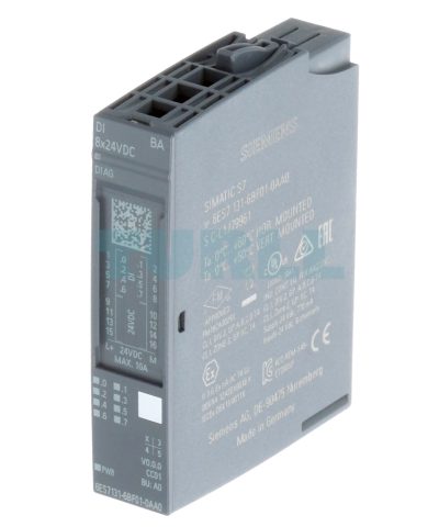
6ES7131-6BF01-0AA0 Siemens SIMATIC ET 200SP Original Brand New
$44.09
6ES7131-6BF01-0AA0 Siemens
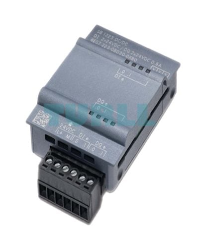
SIMATIC ET 200SP, Digital input module, DI 8x 24V DC Basic, type 2 (IEC 61131), sink input, (PNP, P-reading), Packing unit: 1 piece, fits to BU-type A0, Colour Code CC01, input delay time 0,05..20ms, module diagnostics for: supply voltage

Overview
- 4, 8 and 16-channel digital input (DI) modules
- Apart from the standard type of delivery in single-unit packaging, selected I/O modules and BaseUnits are also available in a pack of 10 units. The pack of 10 units enables the amount of waste to be reduced considerably, as well as saving the time and cost of unpacking individual modules.
Design
Usable BaseUnits (BU)
BaseUnits with an appropriate number of terminals are available for single or multi-conductor connection.
All variants that correspond to the BU type of the I/O module used can be used as BaseUnits (see Selection and ordering data). The BaseUnits that can be used for the respective module are noted on the front side of the module.
Potential distributor modules
With the new potential distributor modules for SIMATIC ET 200SP, additional potentials required within an ET 200SP station can be set up quickly and in a space-saving manner. Due to the free combinability of PotDis-BUs and PotDis-TBs, the potential distributor modules allow a large number of design variants and thus simple adaptation to individual needs.
Within the station, existing potentials can be multiplied or even new potential groups can be formed. With 36 terminals per 15 mm width, the PotDis modules require very little space without compromising on the conductor cross-sections (maximum 2.5 mm²). They allow the connection of voltages up to 48 V DC with a maximum current carrying capacity of 10 A, and with the PotDis-TB-BR-W even up to 230 V AC/10 A as well as the possibility to connect a protective conductor.
Typical applications for the PotDis modules in connection with DI modules are:
- 3-wire connection (signal, 24 V DC, mass) for 16-channel digital input modules with reduced installation height (117 mm instead of 141 mm)
- Connection of non-required switching outputs for antivalent sensors (4-wire connection)
- Supply of supply voltage for sensors
Potential group formation
A light BU separates the self-assembling, internal voltage buses (P1, P2, AUX) and thus opens a new potential group. The supply voltage of a potential group must be fed in at the light BU of this potential group.
A dark BU forwards the supply voltage of the adjacent light BU on the left via the self-assembling voltage buses P1, P2 and AUX. A new infeed is therefore only required on the next light BU to the right. The setting of a further light BU is required whenever
- a new potential group is to be formed (for example, for isolating the supply voltage from module groups) or
- the maximum current simultaneously required by the potential group exceeds the permissible limit of 10 A.
Color identification of the terminals
The potentials at the terminals of the BaseUnit are defined by the inserted I/O module in each case. To prevent wiring faults, the potentials of the terminals can optionally be identified by means of module-specific color-coded labels. The color-coded label that matches the respective I/O module is defined by the color code CCxx of the I/O module. This color code is also printed on the front of the module.
In BaseUnits with the additional ten internally jumpered AUX terminals, these can also be identified with color-coded labels. For the ten AUX terminals, color-coded labels are available in red, blue, and yellow/green.
Download
Visit 6ES7131-6BF01-0AA0
For more products visit turll.com
| Weight | 0.034 kg |
|---|---|
| Dimensions | 68 × 78 × 24 mm |
You must be logged in to post a review.

Reviews
There are no reviews yet.