SIEMENS
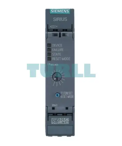
Siemens 3RM1007-1AA04 Direct Starter 500 V, 0.55-3 kW, 24 V DC, Screw Terminal Original Brand New
3RM1007-1AA04
Original price was: $364.06.$152.22Current price is: $152.22.
In stock
SIEMENS
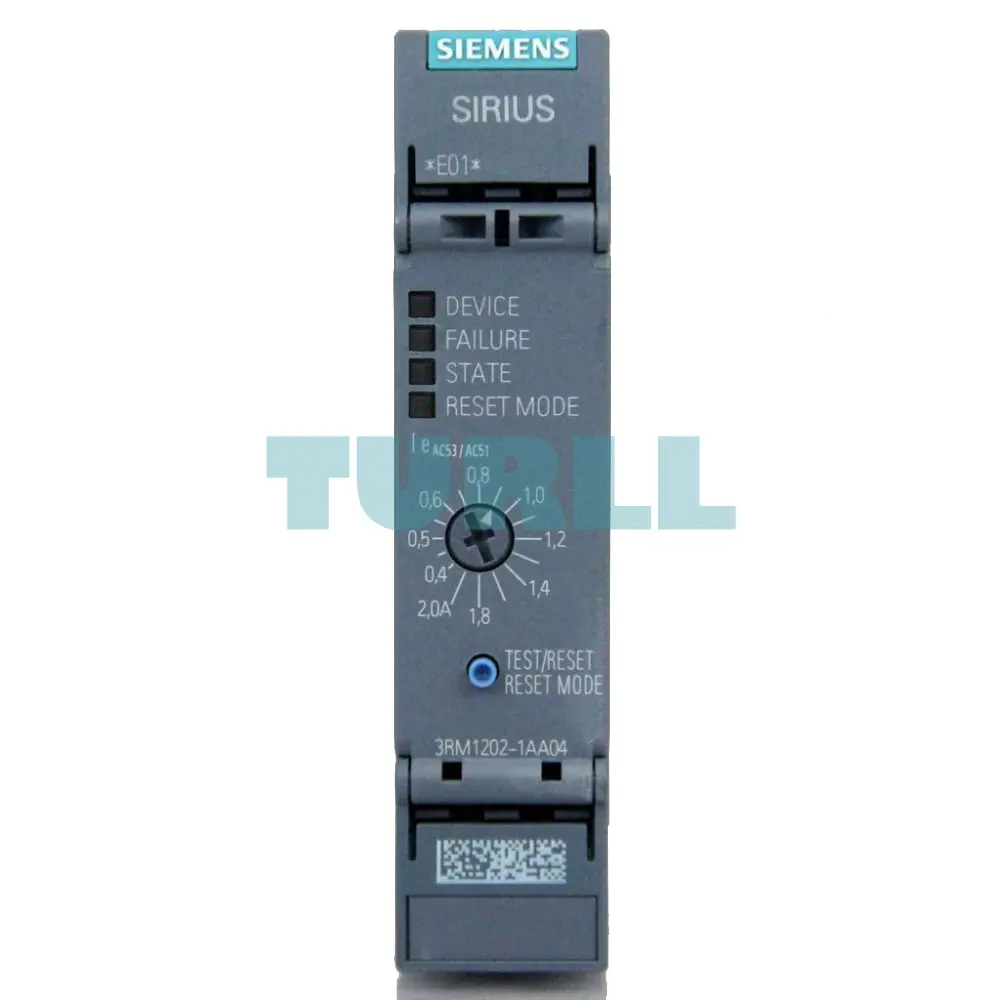
A high-performance SIRIUS 3RM1 compact reversing starter with a robust current setting range of 0.4 to 2 A. Designed for motor loads up to 0.75 kW (500V), this unit features a reliable 24V DC control voltage and secure screw terminals for straightforward installation.
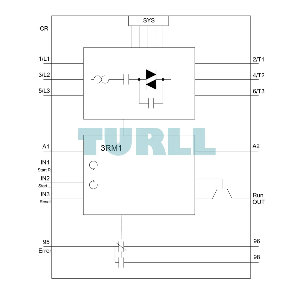
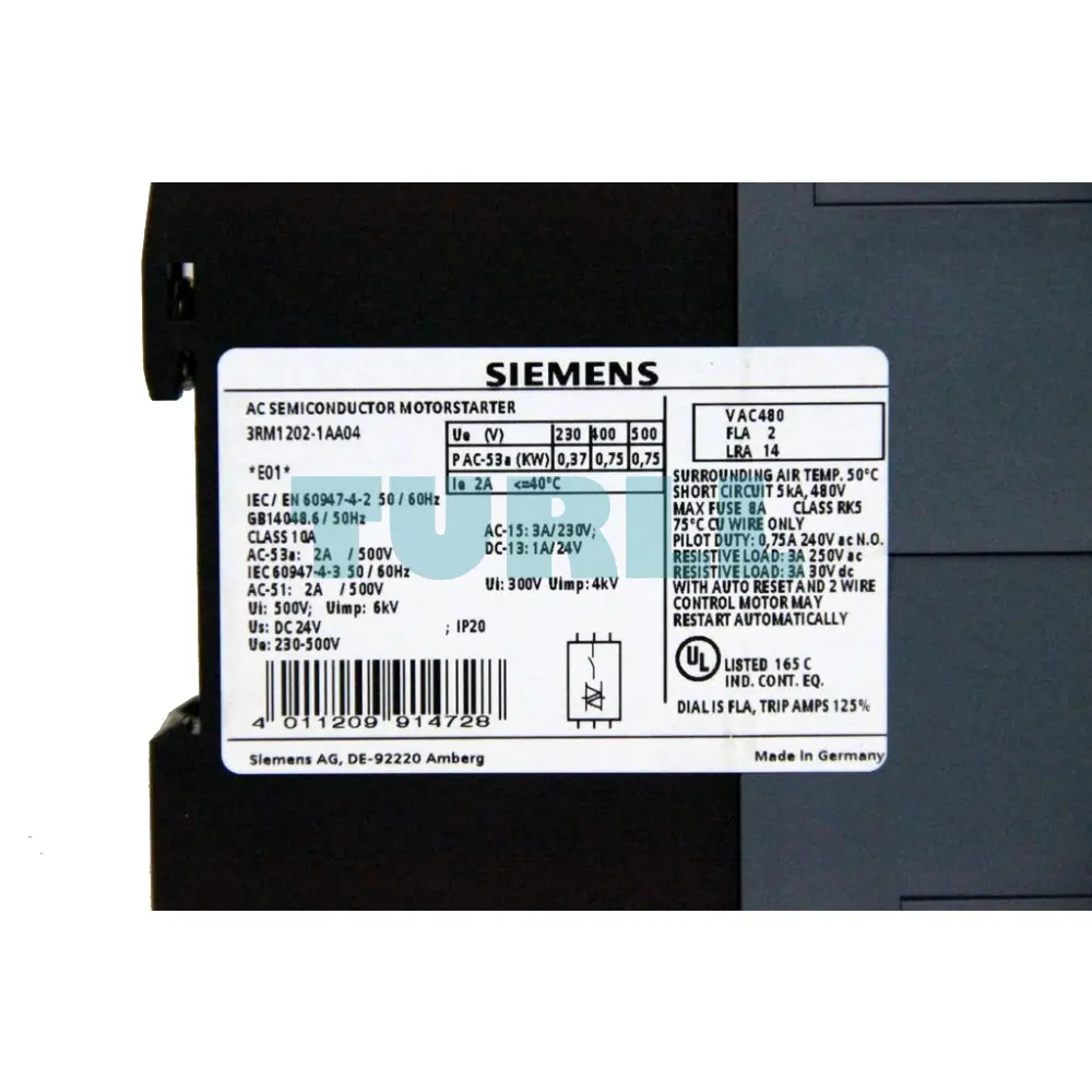
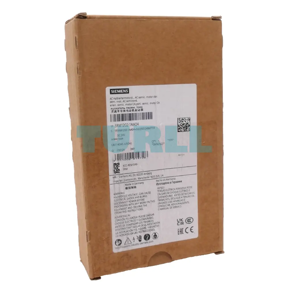
The Siemens 3RM1202-1AA04 Reversing Starter is a compact, highly reliable motor control solution designed for efficient direction switching in industrial applications. As part of the advanced Siemens 3RM1 series, this reversing starter combines high performance with space-saving construction, making it ideal for modern control panel designs. With a voltage rating of 500 V, a power range of 0.09–0.75 kW, and an operating current of 0.4–2 A, it ensures safe and consistent motor operation in demanding environments. Powered by 24 V DC and equipped with easy-to-use screw terminals, it offers simple installation and stable connectivity.
Reliable Motor Reversal: Designed for smooth and safe reversing operations in industrial setups.
Compact and Efficient: Space-saving form factor ideal for small and large control panels.
High Durability: Supports up to 500 V for long-lasting industrial performance.
Versatile Performance Range: Suitable for motors between 0.09–0.75 kW.
Fast Installation: Screw terminals ensure secure, straightforward wiring.
Optimized Safety: Ensures reliable operation within 0.4–2 A current range.
Reversing Motor Starter: Enables forward and reverse motor operation.
Integrated Protection: Ensures safe switching and overload protection (within specified current limits).
24V DC Control Voltage: Provides stable and responsive control signal operation.
Compact 3RM1 Series Design: Saves panel space and reduces wiring complexity.
High Switching Capacity: Suitable for a wide range of industrial motors and automation systems.
Visit 3RM1202-1AA04 for more detail info
For more our products visit turll
| SKU / Model | 3RM1202-1AA04 |
|---|---|
| Brand | SIEMENS |
| product brand name | SIRIUS |
| product category | Motor starter |
| product designation | Reversing starter |
| design of the product | with electronic overload protection |
| product type designation | 3RM1 |
| trip class | CLASS 10A |
| equipment variant acc. to IEC 60947-4-2 | 3 |
| ● intrinsic device protection | Yes |
| ● for power supply reverse polarity protection | No |
| suitability for operation device connector 3ZY12 | Yes |
| power loss [W] for rated value of the current at AC in hot operating state per pole | 0.1 W |
| insulation voltage rated value | 500 V |
| overvoltage category | III |
| surge voltage resistance rated value | 6 kV |
| maximum permissible voltage for safe isolation | - |
| ● between main and auxiliary circuit | 500 V |
| ● between control and auxiliary circuit | 250 V |
| shock resistance | 6g / 11 ms |
| vibration resistance | 1 ... 6 Hz, 15 mm; 20 m/s², 500 Hz |
| operating frequency maximum | 1 1/s |
| mechanical service life (switching cycles) typical | 30 000 000 |
| reference code acc. to IEC 81346-2 | Q |
| product function | - |
| ● direct start | No |
| ● reverse starting | Yes |
| product function short circuit protection | No |
| EMC emitted interference acc. to IEC 60947-1 | class A |
| EMC immunity acc. to IEC 60947-1 | Class A |
| conducted interference | - |
| ● due to burst acc. to IEC 61000-4-4 | 3 kV / 5 kHz |
| ● due to conductor-earth surge acc. to IEC 61000-4-5 | 2 kV |
| ● due to conductor-conductor surge acc. to IEC 61000-4-5 | 1 kV |
| ● due to high-frequency radiation acc. to IEC 61000-4-6 | 10 V |
| field-based interference acc. to IEC 61000-4-3 | 10 V/m |
| electrostatic discharge acc. to IEC 61000-4-2 | 4 kV contact discharge / 8 kV air discharge |
| conducted HF interference emissions acc. to CISPR11 | Class B for the domestic, business and commercial environments |
| field-bound HF interference emission acc. to CISPR11 | Class B for the domestic, business and commercial environments |
| protection class IP on the front acc. to IEC 60529 | IP20 |
| touch protection on the front acc. to IEC 60529 | finger-safe |
| number of poles for main current circuit | 3 |
| design of the switching contact | Hybrid |
| design of the switching contact as NO contact for signaling function | OUT, electronic, 24 V DC, 15 mA |
| adjustable current response value current of the current-dependent overload release | 0.4 ... 2 A |
| minimum load [%] | 20 %; from set rated current |
| type of the motor protection | solid-state |
| operating voltage rated value | 48 ... 500 V |
| relative symmetrical tolerance of the operating voltage | 10 % |
| operating frequency 1 rated value | 50 Hz |
| operating frequency 2 rated value | 60 Hz |
| relative symmetrical tolerance of the operating frequency | 10 % |
| ● at AC at 400 V rated value | 2 A |
| ● at AC-3 at 400 V rated value | 2 A |
| ● at AC-53a at 400 V at ambient temperature 40 °C rated value | 2 A |
| ampacity when starting maximum | 16 A |
| operating power for 3-phase motors at 400 V at 50 Hz | 0.09 ... 0.75 kW |
| input voltage at digital input | - |
| ● at DC rated value | 24 V |
| input current at digital input | - |
| ● for signal <1> at DC | 11 mA |
| ● with signal <0> at DC | 1 mA |
| number of CO contacts for auxiliary contacts | 1 |
| operational current of auxiliary contacts at AC-15 at 230 V maximum | 3 A |
| operational current of auxiliary contacts at DC-13 at 24 V maximum | 1 A |
| type of voltage of the control supply voltage | DC |
| control supply voltage at DC rated value | 19.2 ... 30 V |
| relative negative tolerance of the control supply voltage at DC | 20 % |
| relative positive tolerance of the control supply voltage at DC | 25 % |
| control supply voltage 1 at DC rated value | 24 V |
| operating range factor control supply voltage rated value at DC | - |
| ● initial value | 0.8 |
| ● full-scale value | 1.25 |
| control current at DC | - |
| ● in standby mode of operation | 25 mA |
| ● when switching on | 150 mA |
| duration of inrush current peak at 24 V | 85 ms |
| power loss [W] in auxiliary and control circuit | - |
| ● in switching state OFF | - |
| ● in switching state ON | - |
| — with bypass circuit | 1.68 W |
| ON-delay time | 60 ... 90 ms |
| OFF-delay time | 60 ... 90 ms |
| operational current | - |
| ● at 40 °C rated value | 2 A |
| ● at 50 °C rated value | 2 A |
| ● at 55 °C rated value | 2 A |
| ● at 60 °C rated value | 2 A |
| mounting position | vertical, horizontal, standing (observe derating) |
| fastening method | screw and snap-on mounting onto 35 mm standard mounting rail |
| required spacing | - |
| ● with side-by-side mounting | - |
| ● for grounded parts | - |
| — forwards | 0 mm |
| — backwards | 0 mm |
| — upwards | 50 mm |
| — at the side | 3.5 mm |
| — downwards | 50 mm |
| installation altitude at height above sea level maximum | 4 000 m; For derating see manual |
| ambient temperature | - |
| ● during operation | -25 ... +60 °C |
| ● during storage | -40 ... +70 °C |
| ● during transport | -40 ... +70 °C |
| environmental category during operation acc. to IEC 60721 | 3K6 (no ice formation, only occasional condensation), 3C3 (no salt mist), 3S2 (sand must not get into the devices), 3M6 |
| relative humidity during operation | 10 ... 95 % |
| air pressure acc. to SN 31205 | 900 ... 1 060 hPa |
| protocol is supported | - |
| ● PROFINET IO protocol | No |
| ● PROFIsafe protocol | No |
| product function bus communication | No |
| protocol is supported AS-Interface protocol | No |
| type of electrical connection | screw-type terminals for main circuit, screw-type terminals for control circuit |
| ● for main current circuit | screw-type terminals |
| ● for auxiliary and control circuit | screw-type terminals |
| wire length for motor unshielded maximum | 100 m |
| ● at AWG cables for main contacts | 1x (20 ... 12), 2x (20 ... 14) |
| connectable conductor cross-section for main contacts | - |
| connectable conductor cross-section for auxiliary contacts | - |
| ● solid or stranded | 0.5 ... 2.5 mm² |
| ● finely stranded with core end processing | 0.5 ... 2.5 mm² |
| type of connectable conductor cross-sections | - |
| — solid | 1x (0,5 ... 2,5 mm²), 2x (1,0 ... 1,5 mm²) |
| — finely stranded with core end processing | 1x (0.5 ... 2.5 mm²), 2x (0.5 ... 1 mm²) |
| ● at AWG cables for auxiliary contacts | 1x (20 ... 14), 2x (18 ... 16) |
| AWG number as coded connectable conductor cross section | - |
| ● for main contacts | 20 ... 12 |
| ● for auxiliary contacts | 20 ... 14 |
| yielded mechanical performance [hp] | - |
| ● for single-phase AC motor | - |
| — at 230 V rated value | 0.125 hp |
| ● for 3-phase AC motor | - |
| — at 200/208 V rated value | 0.333 hp |
| — at 220/230 V rated value | 0.333 hp |
| — at 460/480 V rated value | 0.75 hp |
| operating voltage at AC | - |
| ● according to UL rated value | 480 V |
| ● according to CSA rated value | 400 V |
| Test Certificates | Railway other |
| last modified: | 11/3/2021 |
| Weight | 0.329 kg |
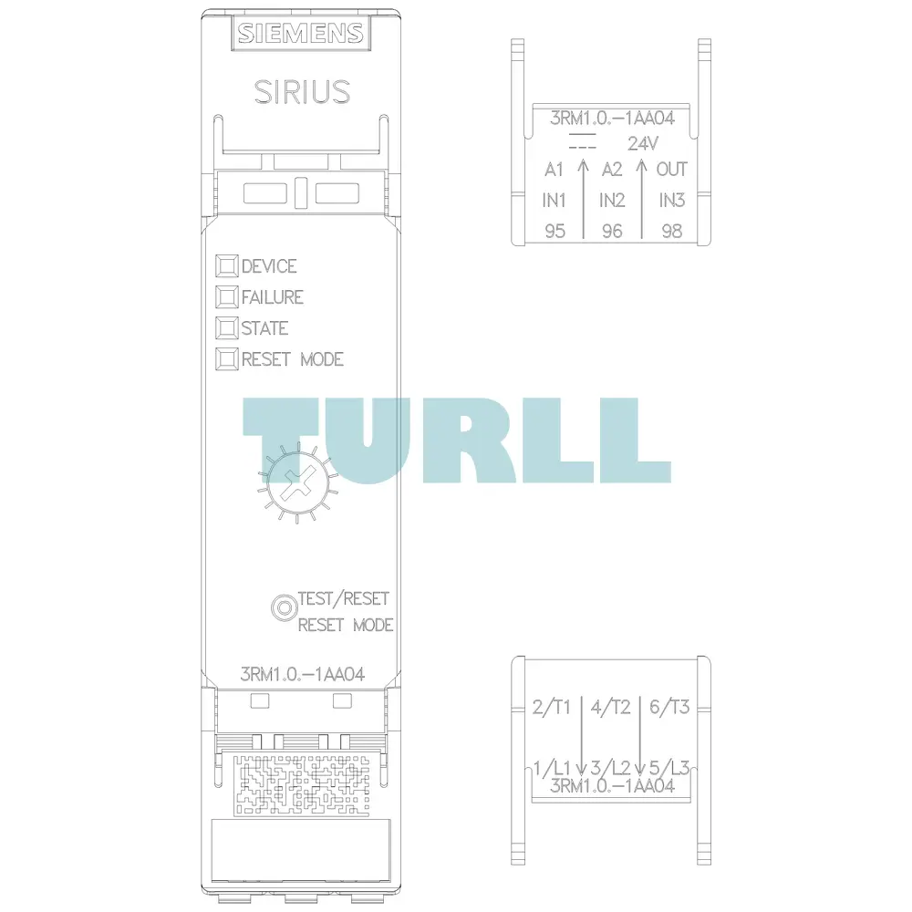
| Dimensions | 36.00 × 109.00 × 167.00 mm |
Request a quote for project quantities, discontinued or obsolete models, and pro-forma invoice / bank transfer orders. Our sourcing team responds fast.