SIEMENS
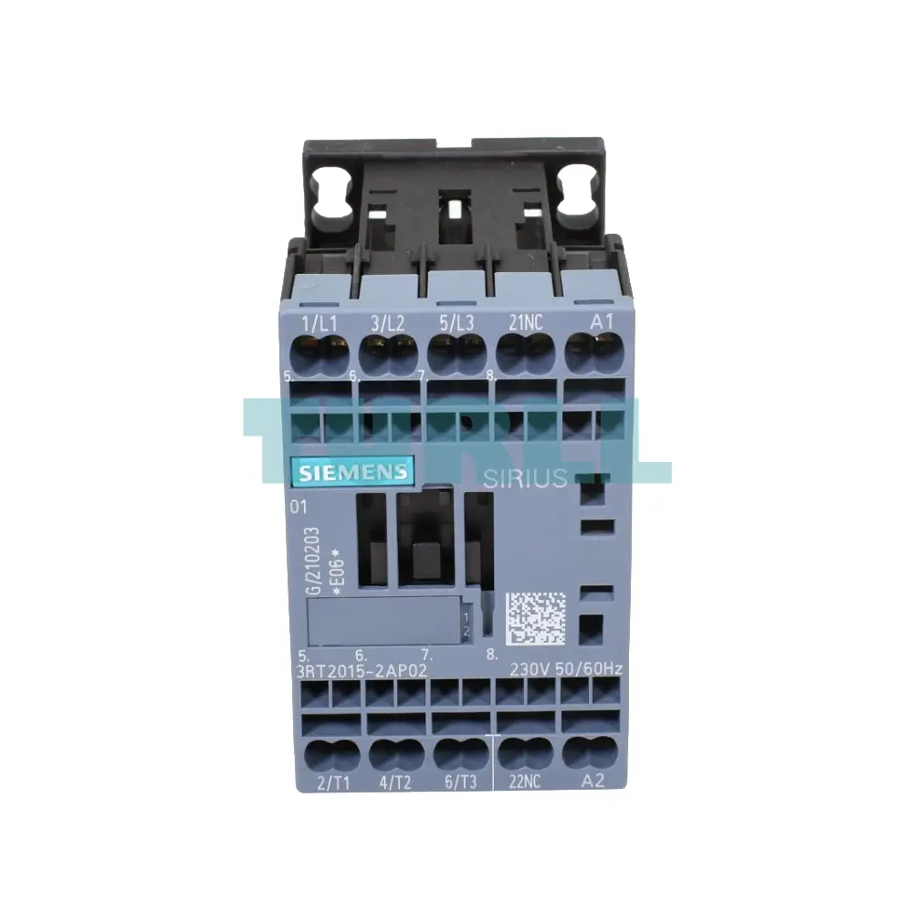
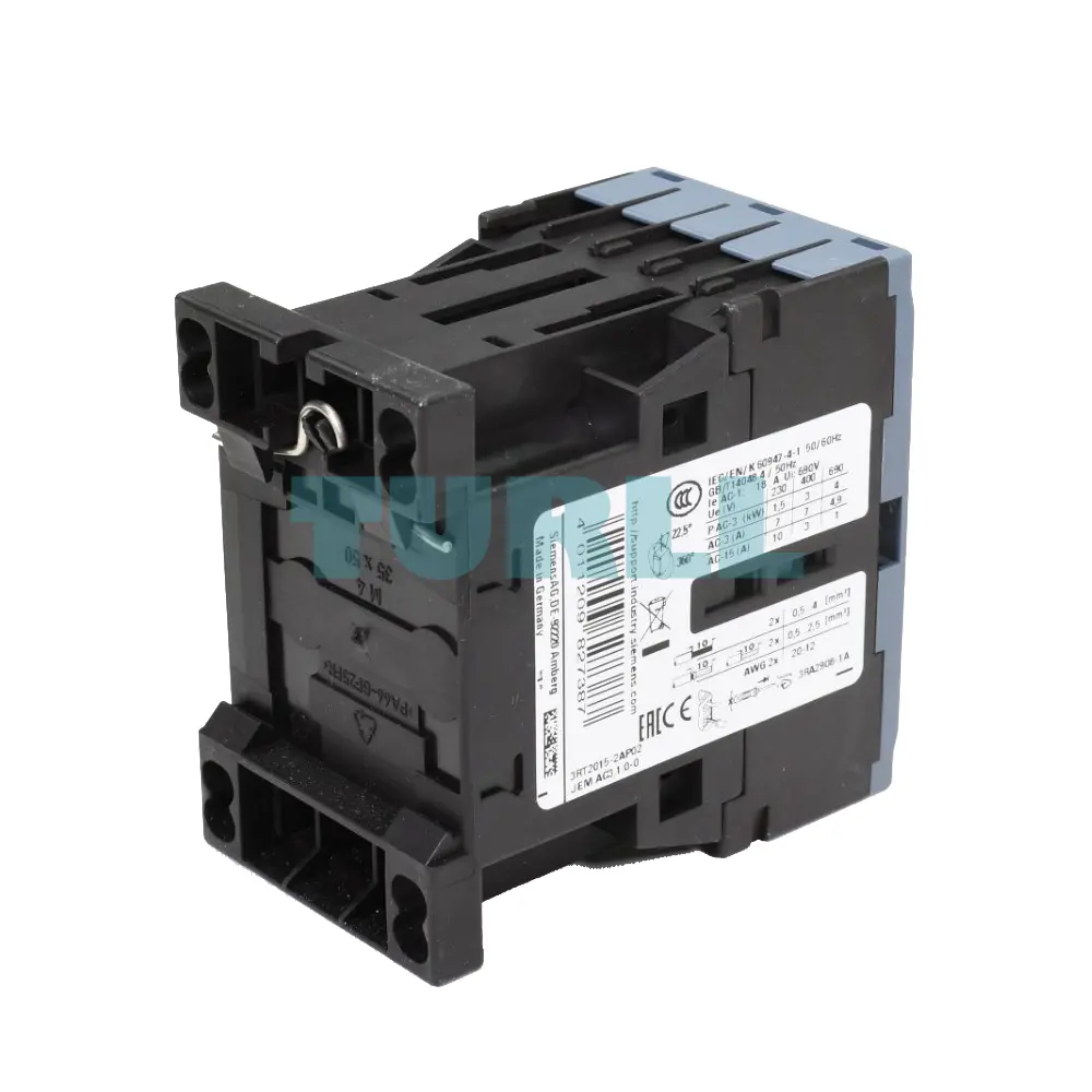
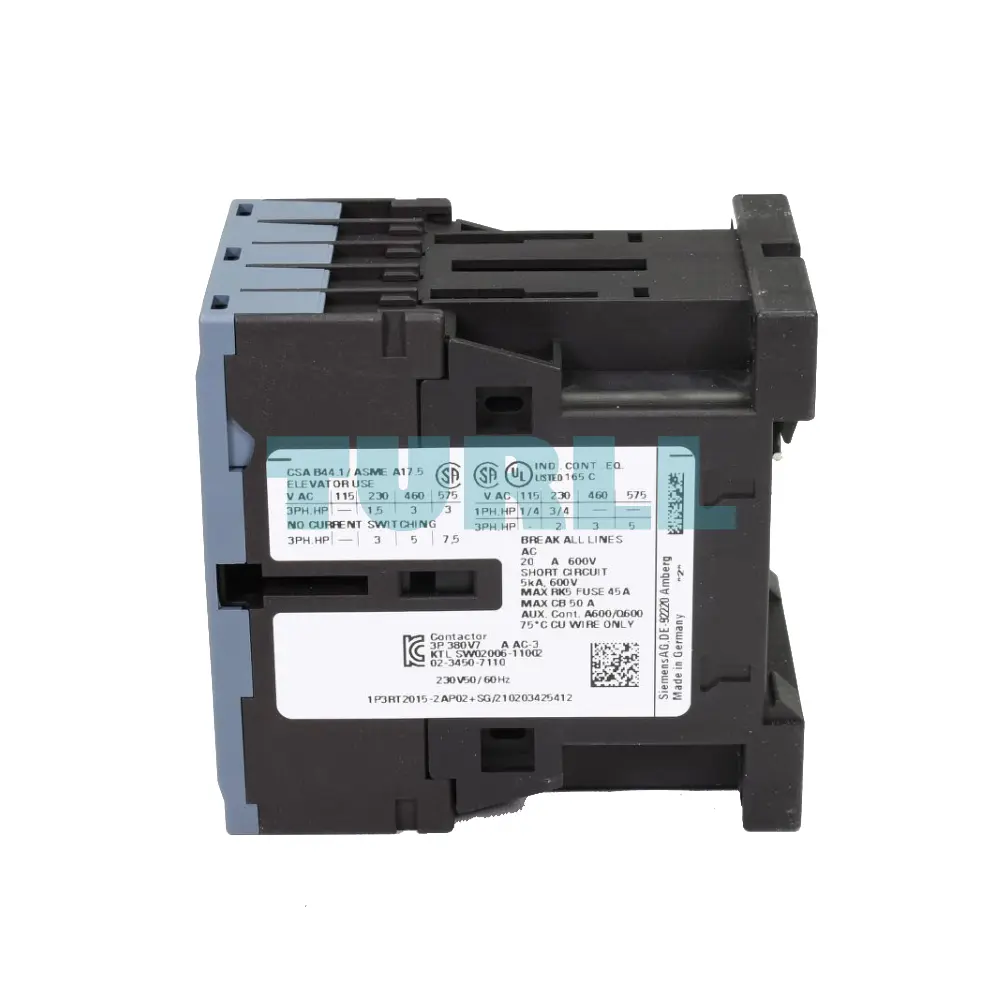
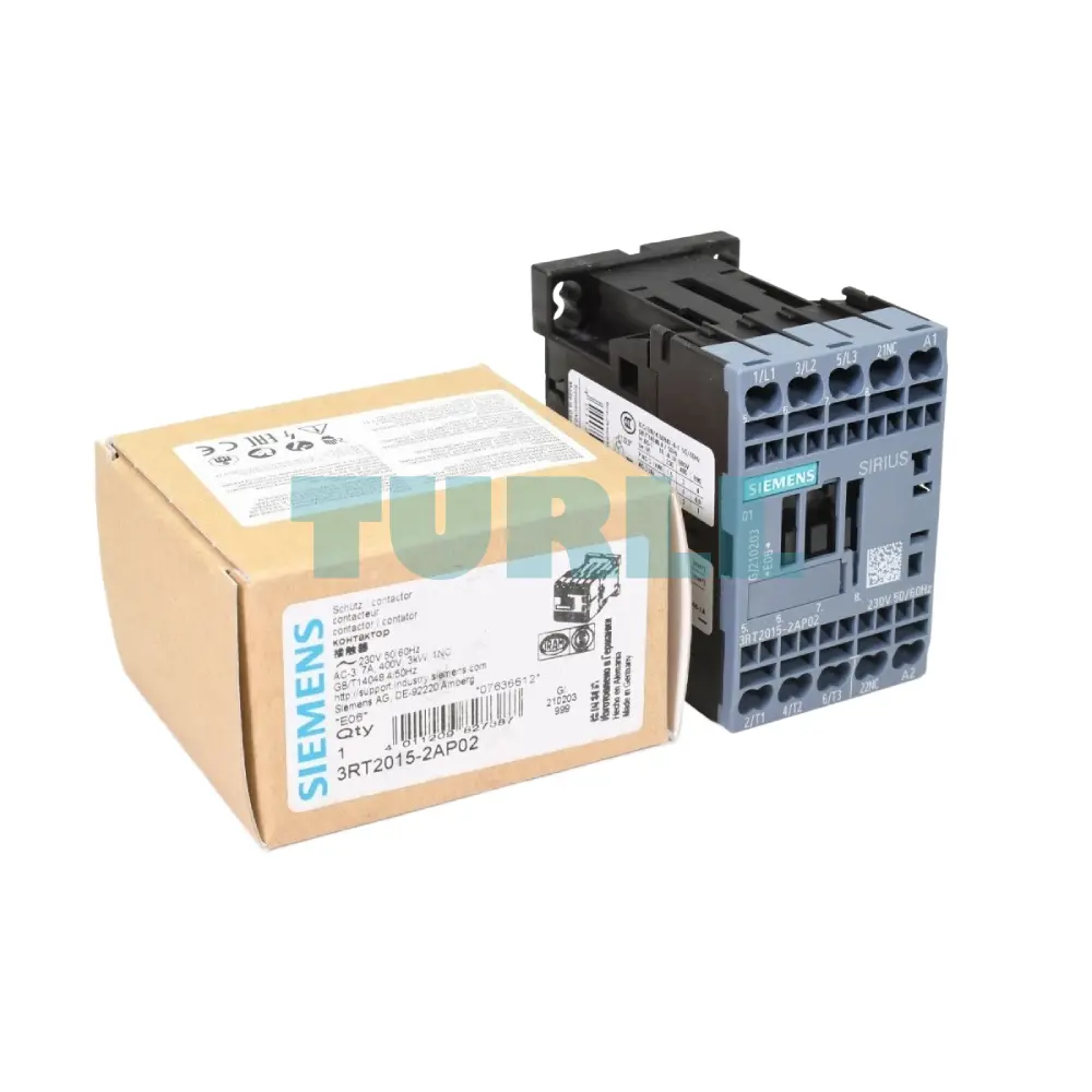
Siemens 3RT2015-2AP02 Power Contactor 7A, 3kW, 3-Pole, 230V AC, S00 Size Original Brand New
High-performance power contactor (Size S00) designed for switching motors up to 3 kW (400 V) or 7 A (AC-3e/AC-3). It features a 230 V AC (50/60 Hz) control voltage, one integrated 1 NC auxiliary contact, and robust spring-loaded terminals for fast, vibration-proof wiring.
- ConditionOriginal Brand New
- Warranty12 months
Backorder available · Factory lead time 2–3 weeks.
- Genuine Products
- Up to 1-Year Warranty
- Global Shipping
- Secure Payment
- PI / Bank Transfer Available
- Bulk Quote Support
Description
Overview
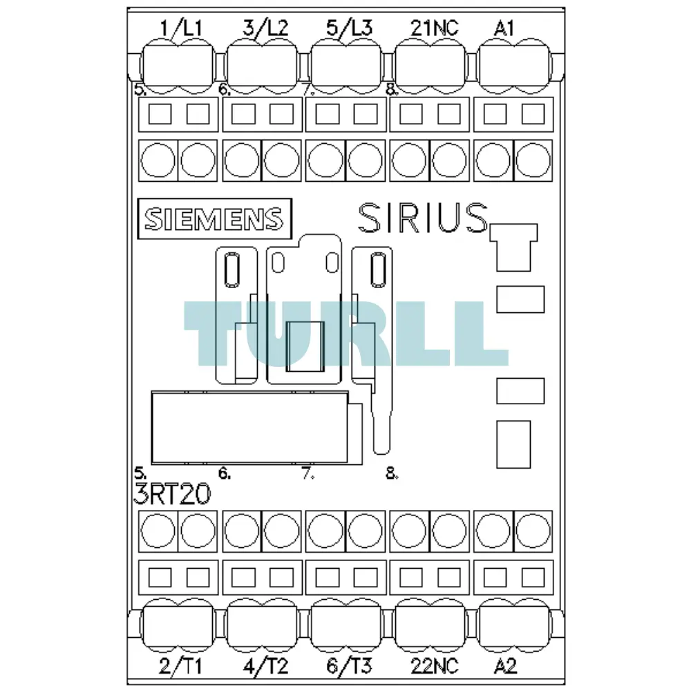
The Siemens 3RT2015-2AP02 is a high-performance power contactor designed for reliable motor switching and control in industrial environments. Engineered for AC-3e/AC-3 applications, it delivers exceptional durability and operational stability. With a compact S00 size, spring-loaded terminals, and built-in auxiliary contacts, this contactor ensures efficient installation and dependable switching performance.
Benefit
-
High Reliability: Built with Siemens' renowned quality, ensuring long mechanical and electrical service life for critical applications.
-
Space-Saving Design: The Size S00 footprint allows for high-density installation in control cabinets, reducing panel size and cost.
-
Fast & Secure Wiring: Spring-loaded terminals eliminate the need for re-tightening, resist vibration, and ensure quick, maintenance-free installation compared to traditional screw terminals.
-
Standardized Integration: Seamless compatibility with the entire SIRIUS modular system (e.g., thermal overload relays, auxiliary switches) for simple assembly and commissioning.
-
Efficient Control: The 230 V AC control coil is a common standard, making integration into existing systems straightforward.
Functionality & Application
The 3RT2015-2AP02 contactor is primarily used for switching three-phase AC motors. It is suitable for applications such as:
-
Controlling pumps, fans, and conveyor systems.
-
General load switching in heating and lighting systems.
-
Use as an actuator in automated processes where reliable ON/OFF control is required.
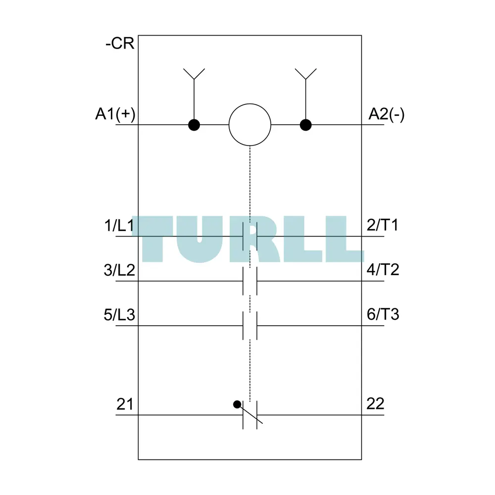
The 1 NC auxiliary contact can be utilized in the safety circuit to confirm that the main power contacts have opened or to interlock with other devices in the control system.
Download
Visit 3RT2015-2AP02 for more detail info
For more our products visit turll
Specifications
| SKU / Model | 3RT2015-2AP02 |
|---|---|
| Brand | SIEMENS |
| product brand name | SIRIUS |
| product designation | Power contactor |
| product type designation | 3RT2 |
| size of contactor | S00 |
| product extension | - |
| ● function module for communication | No |
| ● auxiliary switch | Yes |
| power loss [W] for rated value of the current at AC in hot operating state | 1.2 W |
| ● per pole | 0.4 W |
| power loss [W] for rated value of the current without load current share typical | 4.2 W |
| surge voltage resistance | - |
| ● of main circuit rated value | 6 kV |
| ● of auxiliary circuit rated value | 6 kV |
| maximum permissible voltage for safe isolation between coil and main contacts acc. to EN 60947-1 | 400 V |
| shock resistance at rectangular impulse | - |
| shock resistance with sine pulse | - |
| mechanical service life (switching cycles) | - |
| ● of contactor typical | 30 000 000 |
| ● of the contactor with added electronically optimized auxiliary switch block typical | 5 000 000 |
| ● of the contactor with added auxiliary switch block typical | 10 000 000 |
| reference code acc. to IEC 81346-2 | Q |
| installation altitude at height above sea level maximum | 2 000 m |
| ambient temperature | - |
| ● during operation | -25 ... +60 °C |
| ● during storage | -55 ... +80 °C |
| relative humidity minimum | 10 % |
| relative humidity at 55 °C acc. to IEC 60068-2-30 maximum | 95 % |
| number of poles for main current circuit | 3 |
| number of NO contacts for main contacts | 3 |
| operating voltage at AC-3 rated value maximum | 690 V |
| ● at AC-1 at 400 V at ambient temperature 40 °C rated value | 18 A |
| ● at AC-1 | - |
| — up to 690 V at ambient temperature 40 °C rated value | 18 A |
| — up to 690 V at ambient temperature 60 °C rated value | 16 A |
| ● at AC-4 at 400 V rated value | 6.5 A |
| ● at AC-5a up to 690 V rated value | 15.8 A |
| ● at AC-5b up to 400 V rated value | 5.8 A |
| — up to 230 V for current peak value n=20 rated value | 4 A |
| — up to 400 V for current peak value n=20 rated value | 4 A |
| — up to 500 V for current peak value n=20 rated value | 3.8 A |
| — up to 690 V for current peak value n=20 rated value | 3.6 A |
| ● at AC-6a | - |
| — up to 230 V for current peak value n=30 rated value | 2.7 A |
| — up to 400 V for current peak value n=30 rated value | 2.7 A |
| — up to 500 V for current peak value n=30 rated value | 2.5 A |
| — up to 690 V for current peak value n=30 rated value | 2.4 A |
| minimum cross-section in main circuit at maximum AC-1 rated value | 2.5 mm² |
| operational current for approx. 200000 operating cycles at AC-4 | - |
| operational current | - |
| ● at 1 current path at DC-1 | - |
| ● with 2 current paths in series at DC-1 | - |
| ● with 3 current paths in series at DC-1 | - |
| ● at 1 current path at DC-3 at DC-5 | - |
| ● with 2 current paths in series at DC-3 at DC-5 | - |
| ● with 3 current paths in series at DC-3 at DC-5 | - |
| — at 24 V rated value | 15 A |
| — at 110 V rated value | 15 A |
| — at 220 V rated value | 1.2 A |
| — at 440 V rated value | 0.14 A |
| — at 600 V rated value | 0.14 A |
| operating power | - |
| ● at AC-3 | - |
| — at 400 V rated value | 3 kW |
| — at 500 V rated value | 3 kW |
| — at 690 V rated value | 4 kW |
| operating power for approx. 200000 operating cycles at AC-4 | - |
| ● up to 230 V for current peak value n=20 rated value | 1.5 kV·A |
| ● up to 400 V for current peak value n=20 rated value | 2.7 kV·A |
| ● up to 500 V for current peak value n=20 rated value | 3.3 kV·A |
| ● up to 690 V for current peak value n=20 rated value | 4.3 kV·A |
| operating apparent power at AC-6a | - |
| ● up to 230 V for current peak value n=30 rated value | 1 kV·A |
| ● up to 400 V for current peak value n=30 rated value | 1.8 kV·A |
| ● up to 500 V for current peak value n=30 rated value | 2.2 kV·A |
| ● up to 690 V for current peak value n=30 rated value | 2.9 kV·A |
| short-time withstand current in cold operating state up to 40 °C | - |
| ● limited to 1 s switching at zero current maximum | 120 A; Use minimum cross-section acc. to AC-1 rated value |
| ● limited to 5 s switching at zero current maximum | 86 A; Use minimum cross-section acc. to AC-1 rated value |
| ● limited to 10 s switching at zero current maximum | 67 A; Use minimum cross-section acc. to AC-1 rated value |
| ● limited to 30 s switching at zero current maximum | 52 A; Use minimum cross-section acc. to AC-1 rated value |
| ● limited to 60 s switching at zero current maximum | 43 A; Use minimum cross-section acc. to AC-1 rated value |
| no-load switching frequency | - |
| operating frequency | - |
| ● at AC-1 maximum | 1 000 1/h |
| ● at AC-2 maximum | 750 1/h |
| ● at AC-3 maximum | 750 1/h |
| ● at AC-4 maximum | 250 1/h |
| type of voltage of the control supply voltage | AC |
| control supply voltage at AC | - |
| ● at 50 Hz rated value | 230 V |
| ● at 60 Hz rated value | 230 V |
| operating range factor control supply voltage rated value of magnet coil at AC | - |
| apparent pick-up power of magnet coil at AC | - |
| inductive power factor with closing power of the coil | - |
| apparent holding power of magnet coil at AC | - |
| inductive power factor with the holding power of the coil | - |
| ● at 50 Hz | 0.25 |
| ● at 60 Hz | 0.25 |
| closing delay | - |
| opening delay | - |
| ● at AC | 7 ... 13 ms |
| arcing time | 10 ... 15 ms |
| control version of the switch operating mechanism | Standard A1 - A2 |
| number of NC contacts for auxiliary contacts instantaneous contact | 1 |
| operational current at AC-12 maximum | 10 A |
| operational current at AC-15 | - |
| ● at 230 V rated value | 10 A |
| ● at 400 V rated value | 3 A |
| ● at 500 V rated value | 2 A |
| ● at 690 V rated value | 1 A |
| operational current at DC-12 | - |
| operational current at DC-13 | - |
| ● at 24 V rated value | 10 A |
| ● at 48 V rated value | 2 A |
| ● at 60 V rated value | 2 A |
| ● at 110 V rated value | 1 A |
| ● at 125 V rated value | 0.9 A |
| ● at 220 V rated value | 0.3 A |
| contact reliability of auxiliary contacts | 1 faulty switching per 100 million (17 V, 1 mA) |
| full-load current (FLA) for 3-phase AC motor | - |
| ● at 480 V rated value | 4.8 A |
| ● at 600 V rated value | 6.1 A |
| yielded mechanical performance [hp] | - |
| ● for single-phase AC motor | - |
| — at 110/120 V rated value | 0.25 hp |
| — at 230 V rated value | 0.75 hp |
| ● for 3-phase AC motor | - |
| — at 200/208 V rated value | 1.5 hp |
| — at 220/230 V rated value | 2 hp |
| — at 460/480 V rated value | 3 hp |
| — at 575/600 V rated value | 5 hp |
| contact rating of auxiliary contacts according to UL | A600 / Q600 |
| design of the fuse link | - |
| ● for short-circuit protection of the main circuit | - |
| — with type of coordination 1 required | gG: 35A (690V,100kA), aM: 20A (690V,100kA), BS88: 35A (415V,80kA) |
| — with type of assignment 2 required | gG: 20A (690V,100kA), aM: 16A (690V, 100kA), BS88: 20A (415V, 80kA) |
| ● for short-circuit protection of the auxiliary switch required | gG: 10 A (500 V, 1 kA) |
| mounting position | +/-180° rotation possible on vertical mounting surface; can be tilted forward and backward by +/- 22.5° on vertical mounting surface |
| fastening method | screw and snap-on mounting onto 35 mm standard mounting rail according to DIN EN 60715 |
| ● side-by-side mounting | Yes |
| required spacing | - |
| ● with side-by-side mounting | - |
| ● for grounded parts | - |
| ● for live parts | - |
| — forwards | 10 mm |
| — upwards | 10 mm |
| — downwards | 10 mm |
| — at the side | 6 mm |
| type of electrical connection | - |
| ● for main current circuit | spring-loaded terminals |
| ● for auxiliary and control circuit | spring-loaded terminals |
| ● at contactor for auxiliary contacts | Spring-type terminals |
| ● of magnet coil | Spring-type terminals |
| — solid | 2x (0.5 ... 4 mm²) |
| ● at AWG cables for main contacts | 2x (20 ... 12) |
| connectable conductor cross-section for main contacts | - |
| ● solid | 0.5 ... 4 mm² |
| ● stranded | 0.5 ... 4 mm² |
| connectable conductor cross-section for auxiliary contacts | - |
| ● solid or stranded | 0.5 ... 4 mm² |
| ● finely stranded with core end processing | 0.5 ... 2.5 mm² |
| ● finely stranded without core end processing | 0.5 ... 2.5 mm² |
| type of connectable conductor cross-sections | - |
| — solid or stranded | 2x (0,5 ... 4 mm²) |
| — finely stranded with core end processing | 2x (0.5 ... 2.5 mm²) |
| — finely stranded without core end processing | 2x (0.5 ... 2.5 mm²) |
| ● at AWG cables for auxiliary contacts | 2x (20 ... 12) |
| AWG number as coded connectable conductor cross section | - |
| ● for main contacts | 20 ... 12 |
| ● for auxiliary contacts | 20 ... 12 |
| B10 value with high demand rate acc. to SN 31920 | 1 000 000 |
| proportion of dangerous failures | - |
| ● with low demand rate acc. to SN 31920 | 40 % |
| ● with high demand rate acc. to SN 31920 | 73 % |
| failure rate [FIT] with low demand rate acc. to SN 31920 | 100 FIT |
| T1 value for proof test interval or service life acc. to IEC 61508 | 20 y |
| protection class IP on the front acc. to IEC 60529 | IP20 |
| touch protection on the front acc. to IEC 60529 | finger-safe, for vertical contact from the front |
| suitability for use | - |
| ● safety-related switching OFF | Yes |
| last modified: | 11/17/2021 |
| Weight | 0.251 kg |
| Dimensions | 50.00 × 73.50 × 77.50 mm |
Need bulk pricing or a hard-to-find part?
Request a quote for project quantities, discontinued or obsolete models, and pro-forma invoice / bank transfer orders. Our sourcing team responds fast.