Overview
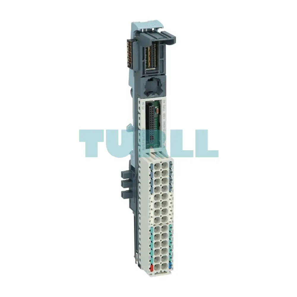
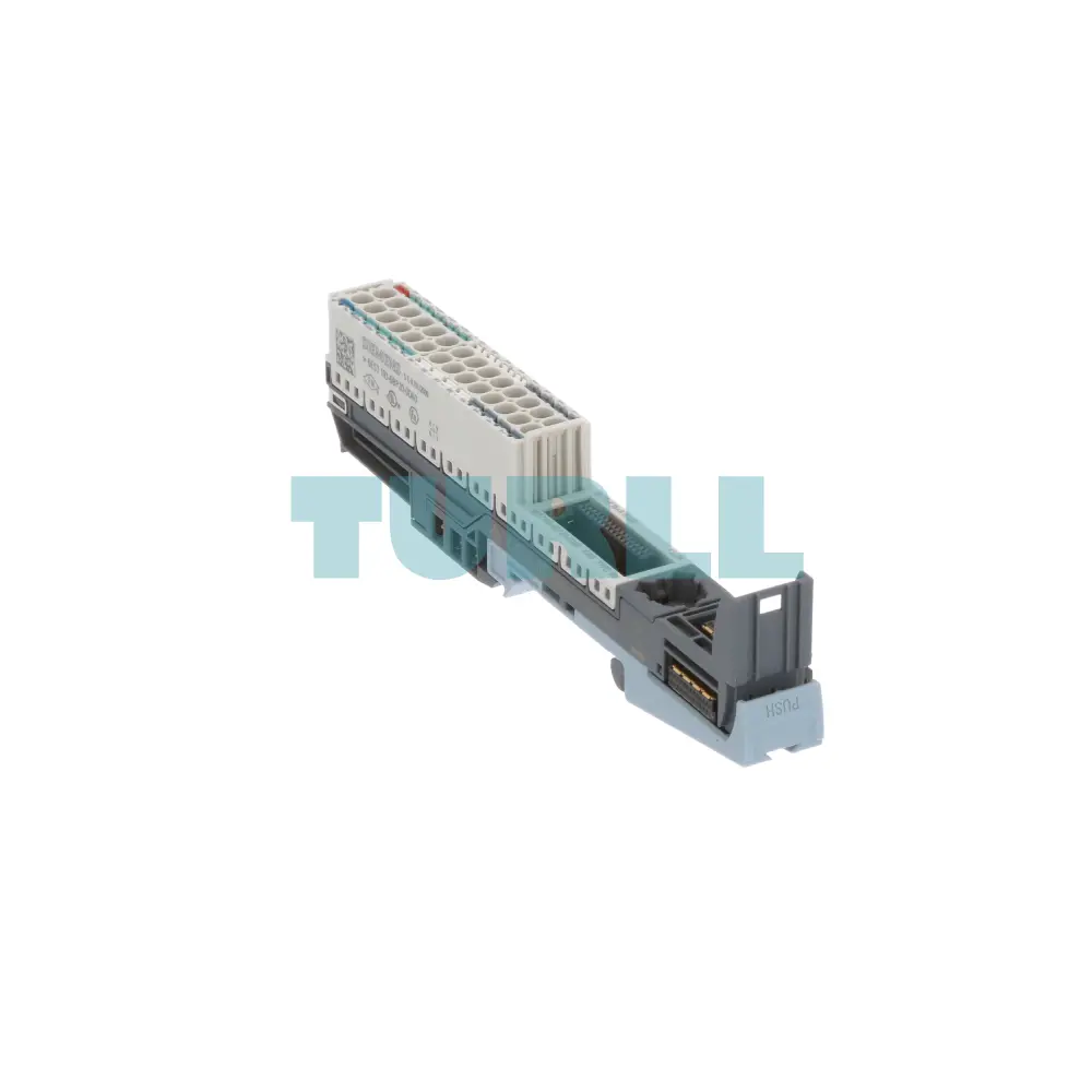
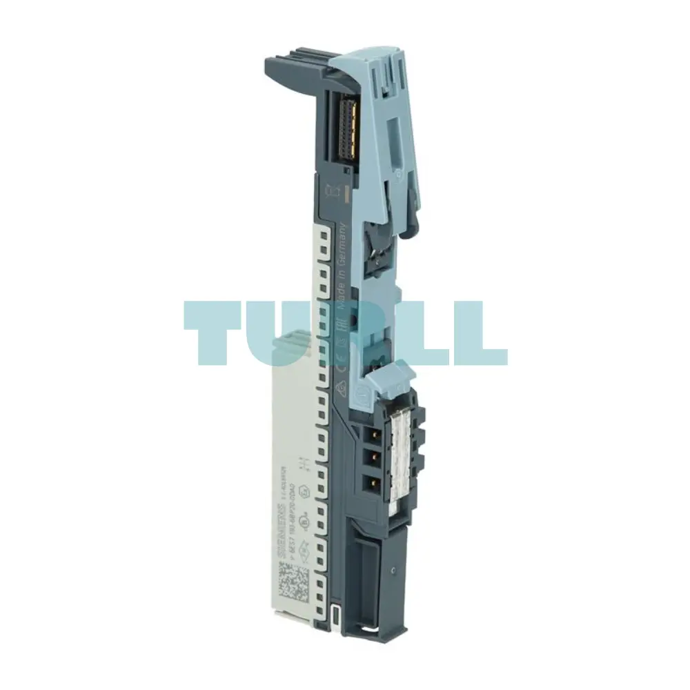
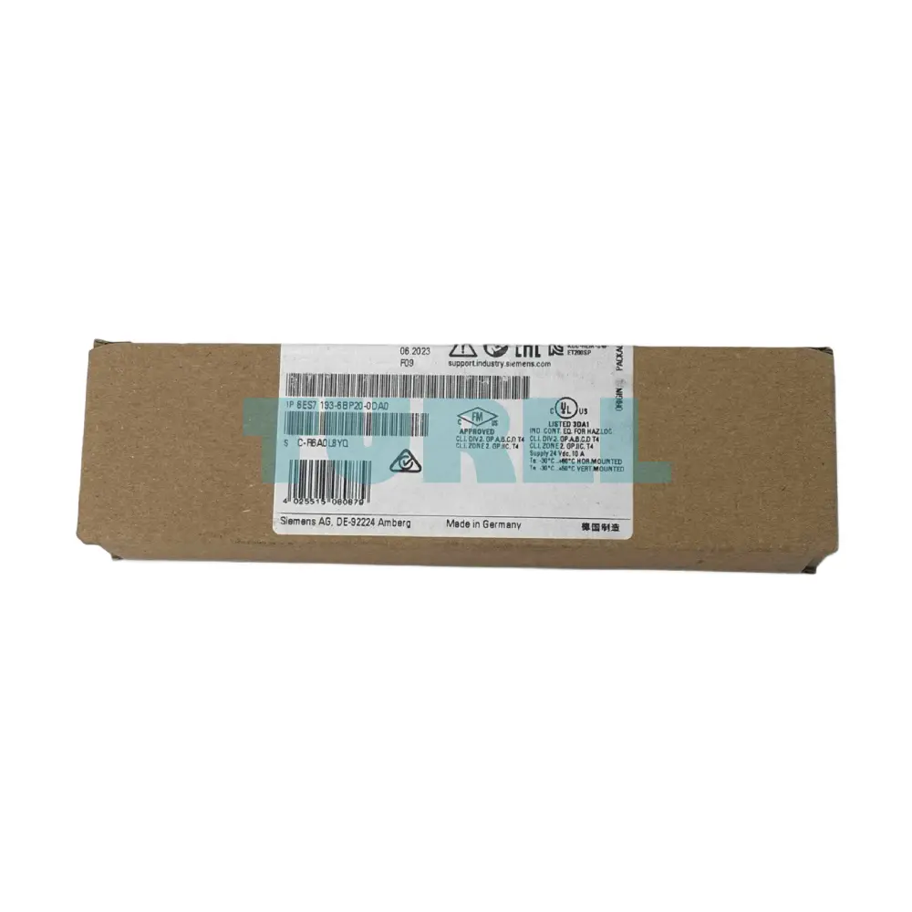
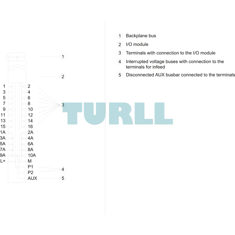
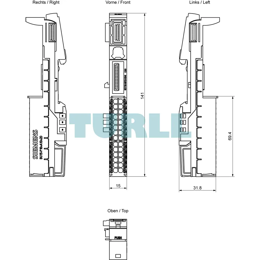
The Siemens 6ES7193-6BP20-0DA0 is a high-performance SIMATIC ET 200SP BaseUnit (BU15-P16+A10+2D) engineered to enhance modular automation systems with superior flexibility, easy wiring, and compact design. Featuring push-in terminals, 10 auxiliary terminals, and a new load group, this BaseUnit ensures reliable and streamlined installation in industrial environments. Its optimized dimensions (15 mm x 141 mm) make it ideal for space-restricted control cabinets.
Key Features
-
BU Type A0 for compatibility across ET 200SP modules
-
Push-in terminal technology for fast, tool-free wiring
-
10 AUX terminals providing extended connection options
-
New load group design improving system flexibility
-
Compact width: Only 15 mm for high-density installations
-
Height: 141 mm, optimal for standardized panel layouts
-
High mechanical durability and secure module locking
Benefit
- Cost & Time Savings: Push-in technology slashes wiring time compared to traditional screw terminals.
- High Flexibility: The 10 AUX terminals (A10) provide dedicated connection points for auxiliary potentials, simplifying complex wiring and field device connections.
- Enhanced System Safety & Reliability: The New Load Group function (D) allows for the creation of clearly defined potential groups, which is critical for fault isolation and maintaining stable system operation.
-
Space Efficiency: With a narrow 15 mm width, the BaseUnit contributes to the compact design of the ET 200SP system, saving valuable cabinet space.
-
Reduced Wiring Errors: Color-coding labels (CC00 to CC09 for process, CC71 to CC73 for AUX) can be applied for fast, error-free module and wiring identification.
Functionality
The Siemens 6ES7193-6BP20-0DA0 BaseUnit serves as the mechanical and electrical foundation for ET 200SP I/O modules. It ensures:
-
Stable module mounting and secure electrical connection
-
Unified internal bus communication for ET 200SP modules
-
Simplified field wiring using front push-in terminals
-
Integration of auxiliary circuits with the 10 AUX terminals
-
Clear wire routing and labeling for maintenance efficiency
Download
Datasheet in PDF
Visit 6ES7193-6BP20-0DA0 for more detail info
For more our products visit turll