


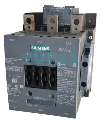
3RT1055-6AF36 Siemens Sirius Power Contactor Original Brand New
$250.64
3RT1055-6AF36 Siemens
power contactor, AC-3e/AC-3 150 A, 75 kW / 400 V AC (50-60 Hz) / DC Uc: 110-127 V 3-pole, auxiliary contacts 2 NO + 2 NC drive: conventional main circuit: busbar control and auxiliary circuit: screw terminal

Overview
Our power range of contactors for switching IE2 motors and highly efficient IE3 and IE4 motors:
- Contactors for switching motors:
- Size S00: 3RT201 up to 7.5 kW
- Size S0: 3RT202 up to 18.5 kW
- Size S2: 3RT203 up to 37 kW
- Size S3: 3RT204 up to 55 kW
- Sizes S6 to S12: 3RT10 up to 250 kW
- SIRIUS 3RT12 and 3TF6 vacuum contactors:
- Sizes S10 and S12: 3RT12 up to 250 kW
- Size 14: 3TF6 up to 450 kW
Standards
IEC 60947‑1, IEC 60947‑4‑1, IEC 60947‑5‑1 (auxiliary switches)
Contactors with increased tamper protection
Increased tamper protection is ensured either by using our contactor versions with factory-installed, permanently mounted auxiliary switches which are protected against mechanical external actuation (e.g. 3RT20..‑…..‑3MA0 or 3RT10..‑…..‑3PA0 contactors), or by using the 3RT2916‑4MA10 or 3RT1926‑4MA10 sealable cover as an accessory.
Operating times
Protection of the device connections against short circuit, overload, and overvoltage
All connections must generally be protected against overload and short circuits using suitable measures. Different constraints must be considered depending on the type of connection:
Short-circuit and overload protection of main connections
For information on the protection of a free-standing contactor, see the technical product data sheet.
For more information on device combinations such as contactor with overload relay or contactor with circuit breaker as motor feeder, refer to
Short-circuit and overload protection of auxiliary connections
For information on the protection of auxiliary contacts, see the technical product data sheet.
Short-circuit and overload protection of control supply voltage or supply voltage connections
First of all, the relevant standards and regulations for configuring control panels and the parts and components installed in them must be taken into account, for example for cable dimensioning.
One possible protection for these circuits could be the selection of a suitable power supply, i.e. one with a current-limiting function. In the selection of the source and the connecting cable, the load characteristics of the contactor must be considered (short-time inrush current peaks for solid-state contactor operating mechanisms, switch-on power, holding power). The same applies to the selection of suitable protection devices.
If there are further switching elements in the circuit, such as the auxiliary contact system of an overload relay that operates the contactor, the short-circuit protection necessary for this must also be considered.
For further recommendations, e.g. the use of miniature or circuit breakers for equipment in control circuits, see Control panel tip – Selecting and dimensioning suitable power supplies quickly and reliably.
Short-circuit and overload protection of contactors with digital input
According to the PLC input types specified in IEC 60947‑4‑1, a typical rated current of 20 mA applies to these inputs. The inputs can be protected accordingly.
- Contactors with PLC and F‑PLC inputs:
- For 3RT10..‑.P marked with IN+/IN-
- For 3RT10..‑.S, ‑.N and 3RT20..‑.S marked with +/-
- Supply voltage connections A1 – A2:
- For 3RT10..‑.N, ‑.P and 3RT20..‑.S, protection must be provided according to load characteristics.
For information on power consumption, see the technical product data sheet. - With 3RT10..‑.S, the protection is already integrated.
- For 3RT10..‑.N, ‑.P and 3RT20..‑.S, protection must be provided according to load characteristics.
Short-circuit and overload protection of other connections
The contactor version 3RT10..‑.P with remaining lifetime indicator (RLT) has additional connections H1 – H2 and R1 – R2.
If A1 – A2 is already protected, further protection of H1 – H2 is not required.
For information on the protection of R1 – R2, see the technical product data sheet.
Protection against overvoltage at the control supply voltage connection
3RT20 contactors supplied without a coil circuit can be retrofitted with RC elements, varistors, diodes or diode assemblies (assembly of diode and Zener diode for short break times) for damping opening surges in the coil and must be ordered separately as accessory, see Surge suppressors.
The 3RT10 contactors are already equipped with coil damping (varistor).
Note:
The break times of the contactor, the opening delay times of the NO contacts and the closing delay times of the NC contacts increase with damping.
For more information on how damping influences the time response, see the Equipment Manual.
Connection methods
Main circuit
- 3RT201 and 3RT202 contactors:
Screw terminals or spring-loaded terminals;
spring-loaded terminals with convenient plug-in design for device connectors - 3RT203 and 3RT204 contactors:
Screw terminals with box terminal;
direct connection to the connecting bar possible with cable lugs for 3RT204 when the box terminal is removed. - 3RT10 contactors:
Screw terminals with connecting bars that the cables can be connected to using either cable lugs or flexible or rigid busbars. Alternatively, box terminals are available as accessories.
Auxiliary and control circuit
The 3RT contactors are available with screw terminals or spring-loaded terminals.
Electromagnetic compatibility
The contactors fulfill the requirements for environment category A.
Note:
When the contactors are used in an environment with frequency converters, the configuration notes must be observed, see Equipment Manual.
Contact reliability of auxiliary contacts
If voltages ≤ 110 V and currents ≤ 100 mA are to be switched, the auxiliary contacts of the 3RT contactors or 3RH contactor relays should be used as they guarantee a high level of contact reliability.
These auxiliary contacts are especially suitable for solid-state circuits with currents ≥ 1 mA at a voltage of 17 V and higher.
Motor protection
3RT20 contactors
For protection against overload, 3RU2 thermal overload relays or 3RB3 electronic overload relays can be mounted on the 3RT20 contactors.
3RT10 contactors
For protection against overload, 3RB2 electronic overload relays can be mounted on the 3RT10 contactors.
Plant and application monitoring
For monitoring and measuring in the application, the 3RR2 monitoring relays can be mounted on the 3RT20 contactors.
Contactors with voltage tap-off
The 3RT20 contactors with voltage tap-off are special versions for mounting the SIRIUS 3RA27 function modules for connection to the control system via IO‑Link or AS‑Interface.
Without a function module, these contactors can be used like the standard versions.
For more information on IO‑Link and AS‑Interface.
Operating mechanism types
3RT20 contactors
The standard versions are available with AC or DC operating mechanisms or as contactor versions with a wide-range solid-state operating mechanism and a universal actuating voltage (AC or DC operation possible).
Versions with solid-state operating mechanisms for AC or DC operation with a fail-safe PLC input are also available for the 3RT203 and 3RT204 contactors.
Control takes place via the control supply voltage connection A1 – A2 with varying operating ranges (see the technical product data sheet for further details).
DC coupling contactors with reduced power consumption are also ideally suited for connection to the controller.
3RT10 contactors
The operating mechanisms are powered via a supply voltage with an operating range from 0.8 to 1.1 x Us, optionally also controlled depending on the chosen mode of operation. Various rated voltage ranges are available for AC/DC control.
The following control and/or operating mechanism versions can be selected for contactors 3RT105 to 3RT107:
- 3RT10..-.A contactors:
Standard operating mechanism for AC and DC operation (reduced closing and holding power) - Solid-state operating mechanisms:
Overvoltage damping of the operating mechanism coil is already integrated in the electronics for contactors with solid-state operating mechanisms.
The following versions are available:- 3RT10..‑.N contactors:
With two operating modes: Direct control or via PLC input (24 V DC) - 3RT10..-.P contactors:
Control via PLC input (24 V DC) only, but with additional remaining lifetime indicator (RLT) - 3RT10..-.S contactors:
Control via fail-safe PLC input (24 V DC) only, for simplification of safety applications (without operating mode selection)
- 3RT10..‑.N contactors:
Replacing solenoid coils, operating mechanisms, or spare contacts
3RT20 contactors
Coil replacement is possible for contactors 3RT202 to 3RT204.
NOTICE:
Removal or changing of the operating mechanism or spare contacts is not permitted for 3RT20..‑.S contactors with fail-safe control.
3RT10 contactors
The operating mechanisms for 3RT10..‑.A/‑.N/‑.P contactors are removable and can be replaced simply by unlocking and pulling them out.
NOTICE:
Removal or changing of the operating mechanism is not permitted for 3RT10..‑.S contactors with fail-safe control.
Fitting auxiliary contacts and mounting additional auxiliary switches
Equipment as supplied
- 3RT20 contactors:
- 3RT201 contactor:
An auxiliary contact is integrated in the basic unit. - 3RT202 to 3RT204 contactors:
The basic units contain two integrated auxiliary contacts (1 NO + 1 NC).
- 3RT201 contactor:
- 3RT10 contactors:
These contactors are supplied with two laterally mounted auxiliary switches. The fitting of auxiliary switches is possible on the front and on the side.
Expansion possibilities
All basic units (with the exception of coupling contactors in sizes S00 and S0) can be expanded using auxiliary switches. The permitted configuration must be taken into account.
For detailed information on fitting auxiliary switches for 3RT20 contactors
Connection of contactors to fail-safe control modules
While contactors with smaller power ratings can be connected directly to the outputs of fail-safe controllers, implementing safety-related applications with standard contactors with higher power is much more complicated and elaborate because of the necessary coupling links.
Due to their fail-safe control input, special contactors provide a much simpler way of doing this:
- 3RT20..‑.S contactors in sizes S2 and S3
- 3RT10..‑.S contactors in sizes S6 to S12
3RT1055-6AF36 Siemens
Siemens power contactor, AC-3e/AC-3 150 A, 75 kW / 400 V AC (50-60 Hz) / DC Uc: 110-127 V 3-pole, auxiliary contacts 2 NO + 2 NC drive: conventional main circuit: busbar control and auxiliary circuit: screw terminal
| Weight | 3.36 kg |
|---|---|
| Dimensions | 190 × 129 × 181 mm |
You must be logged in to post a review.

Reviews
There are no reviews yet.