SIEMENS
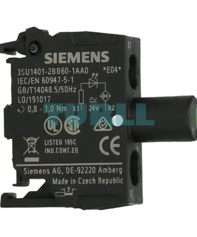
Siemens 3SU1401-2BB60-1AA0 LED Module 24V AC/DC, White, Integrated LED, Screw Terminal Original Brand New
3SU1401-2BB60-1AA0
Original price was: $8.74.$3.50Current price is: $3.50.
In stock
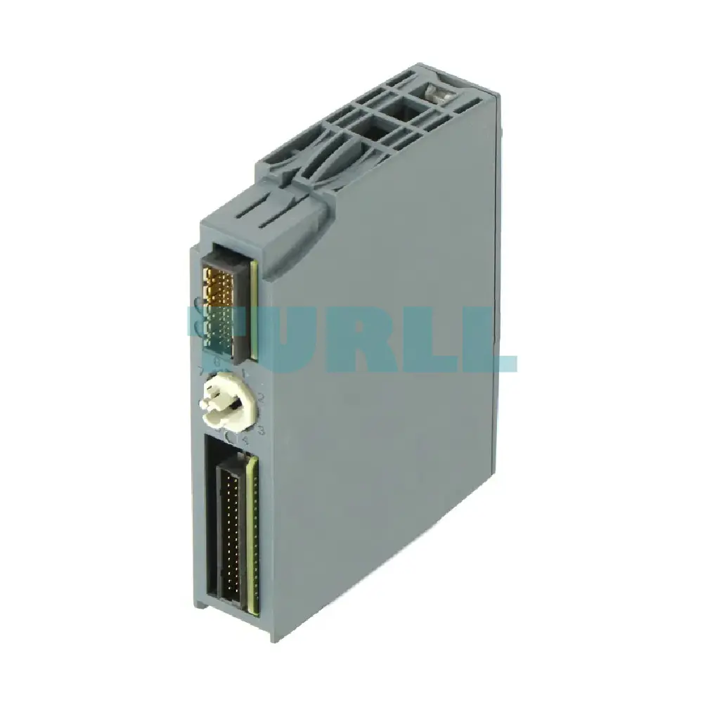
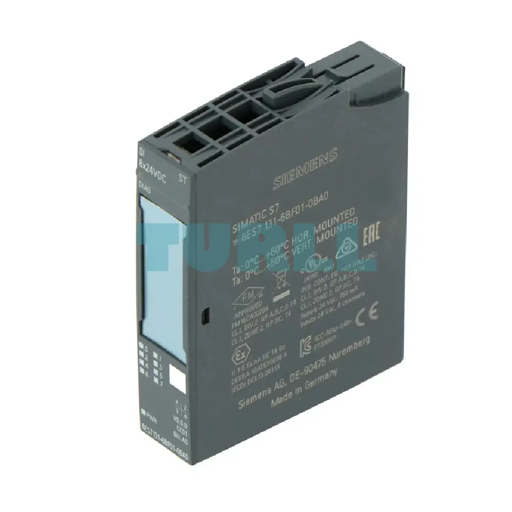
SIEMENS
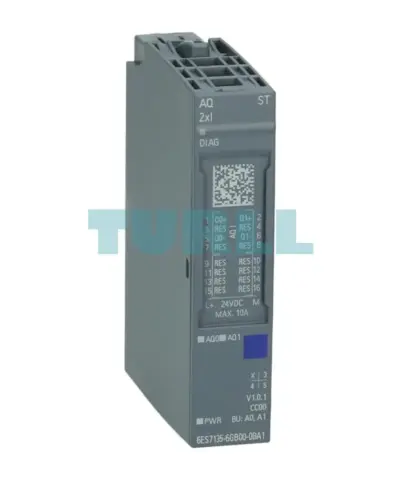
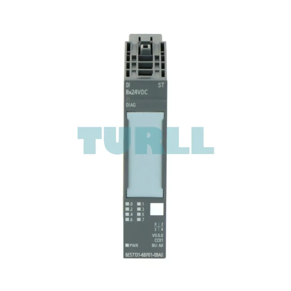
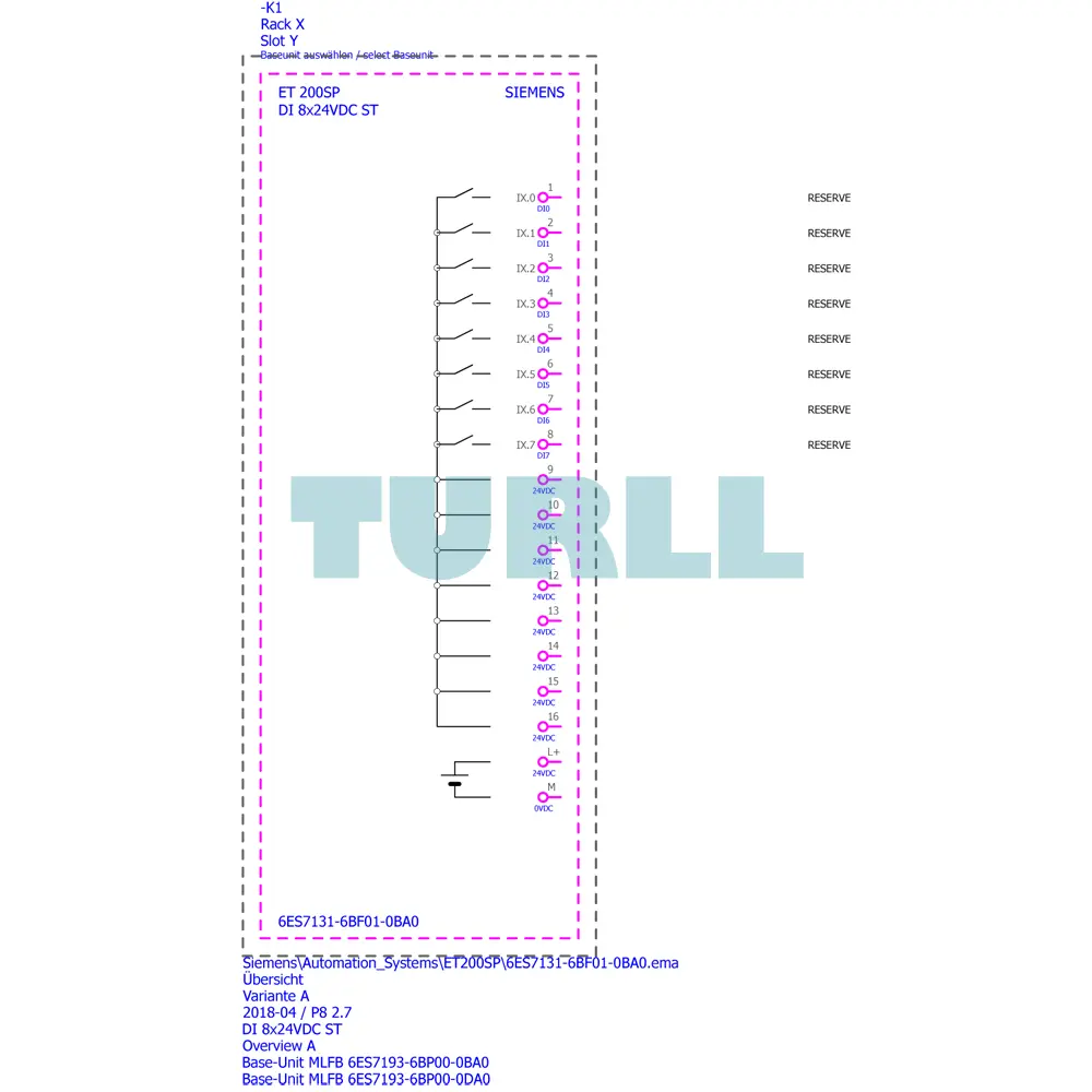
Digital Input Module for SIMATIC ET 200SP. Features 8x 24 V DC Type 3 (IEC 61131) inputs, PNP (sink) configuration, adjustable input delay, and full diagnostic functions. Compatible with BU-type A0 and marked with Colour Code CC01.
The Siemens 6ES7131-6BF01-0BA0 is a high-performance SIMATIC ET 200SP Digital Input Module designed for modern, decentralized automation systems. Featuring 8 digital inputs at 24 V DC (Type 3 IEC 61131), this module delivers reliable signal acquisition with exceptional accuracy and fast response times. Engineered for industrial efficiency, it supports sink (PNP) inputs and offers a robust diagnostic suite to ensure maximum operational uptime.
The module is compatible with BU-type A0 and features Colour Code CC01, enabling seamless integration and easy identification within your ET 200SP system. With an adjustable input delay time of 0.05 to 20 ms, it ensures precise filtering of noisy signals for smooth and stable machine operation.
High System Availability: Integrated module diagnostics (short-circuit of sensor supply, wire break, supply voltage monitoring) allow for quick fault identification, minimizing downtime.
Space-Saving Design: The compact form factor of the ET 200SP system significantly reduces control cabinet size compared to traditional I/O solutions.
Flexible Integration: Features 8 digital input channels (DI 8x 24V DC) with a flexible, adjustable input delay time (0.05ms to 20ms) for matching various sensor types and application speeds.
Simple Installation: Designed to fit the standardized BU-type A0 BaseUnit, facilitating easy module replacement (hot swapping) and reduced wiring effort.
Industry Standard Compliance: Type 3 (IEC 61131) compliance ensures compatibility and reliability within standard automation architectures.
The DI 8x 24V DC Standard Module functions as the digital gateway for your automation process. It takes input signals from field devices (e.g., limit switches, proximity sensors) with a nominal 24V DC voltage and transmits the binary state to the central controller (e.g., SIMATIC S7-1500/1200). It operates as a sink input (PNP, P-reading), meaning it monitors a positive voltage signal coming from the sensor. The adjustable input delay time helps filter out signal noise or adapt to the required cycle time.
Visit 6ES7131-6BF01-0BA0 for more detail info
For more our products visit turll
| SKU / Model | 6ES7131-6BF01-0BA0 |
|---|---|
| Brand | SIEMENS |
| Product type designation | DI 8x24 VDC ST |
| HW functional status | From FS02 |
| Firmware version | V0.0 |
| ● FW update possible | No |
| usable BaseUnits | BU type A0 |
| Color code for module-specific color identification plate | CC01 |
| ● I&M data | Yes; I&M0 to I&M3 |
| ● Isochronous mode | No |
| ● STEP 7 TIA Portal configurable/integrated from version | V14 |
| ● STEP 7 configurable/integrated from version | V5.5 SP3 or higher |
| ● PCS 7 configurable/integrated from version | V8.1 SP1 |
| ● PROFIBUS from GSD version/GSD revision | One GSD file each, Revision 3 and 5 and higher |
| ● PROFINET from GSD version/GSD revision | GSDML V2.3 |
| ● DI | Yes |
| ● Counter | No |
| ● Oversampling | No |
| ● MSI | No |
| Rated value (DC) | 24 V |
| permissible range, lower limit (DC) | 19.2 V |
| permissible range, upper limit (DC) | 28.8 V |
| Reverse polarity protection | Yes |
| Current consumption, max. | 50 mA; All channels are supplied from the encoder supply |
| Number of outputs | 8 |
| Output voltage, min. | 19.2 V |
| Short-circuit protection | Yes; per module |
| ● 24 V | Yes |
| ● Short-circuit protection | Yes |
| ● Output current, max. | 700 mA |
| ● Output current per channel, max. | 700 mA |
| ● Output current per module, max. | 700 mA |
| Power loss, typ. | 1 W; 24 V, 8 inputs supplied via encoder supply |
| ● Inputs | 1 byte; + 1 byte for QI information |
| Automatic encoding | Yes |
| ● Mechanical coding element | Yes |
| ● Type of mechanical coding element | Type A |
| ● 1-wire connection | BU type A0 |
| ● 2-wire connection | BU type A0 |
| ● 3-wire connection | BU type A0 with AUX terminals or potential distributor module |
| ● 4-wire connection | BU type A0 + Potential distributor module |
| Number of digital inputs | 8 |
| Digital inputs, parameterizable | Yes |
| Source/sink input | P-reading |
| Input characteristic curve in accordance with IEC 61131, type 3 | Yes |
| ● Rated value (DC) | 24 V |
| ● for signal "0" | -30 to +5 V |
| ● for signal "1" | +11 to +30V |
| ● for signal "1", typ. | 2.5 mA |
| — at "0" to "1", min. | 0.05 ms |
| — at "0" to "1", max. | 20 ms |
| — at "1" to "0", min. | 0.05 ms |
| — at "1" to "0", max. | 20 ms |
| ● shielded, max. | 1 000 m |
| ● unshielded, max. | 600 m |
| ● 2-wire sensor | Yes |
| — permissible quiescent current (2-wire sensor), max. | 1.5 mA |
| Diagnostics function | Yes |
| ● Diagnostic alarm | Yes |
| ● Diagnostic information readable | Yes |
| ● Monitoring the supply voltage | Yes |
| — parameterizable | Yes |
| ● Monitoring of encoder power supply | Yes; Module-by-module, optional protective circuit for preventing wire-break diagnostics in the case of simple encoder contacts: 25 kOhm to 45 kOhm |
| ● Wire-break | Yes; Module-wise |
| ● Short-circuit | Yes; Module-wise |
| ● Monitoring of the supply voltage (PWR-LED) | Yes; green PWR LED |
| ● Channel status display | Yes; green LED |
| ● for channel diagnostics | No |
| ● for module diagnostics | Yes; green/red DIAG LED |
| ● between the channels | No |
| ● between the channels and backplane bus | Yes |
| ● between the channels and the power supply of the electronics | No |
| Isolation tested with | 707 V DC (type test) |
| Suitable for safety functions | No |
| ● horizontal installation, min. | -30 °C; < 0 °C as of FS02 |
| ● horizontal installation, max. | 60 °C |
| ● vertical installation, min. | -30 °C; < 0 °C as of FS02 |
| ● vertical installation, max. | 50 °C |
| ● Installation altitude above sea level, max. | 5 000 m; Restrictions for installation altitudes > 2 000 m, see manual |
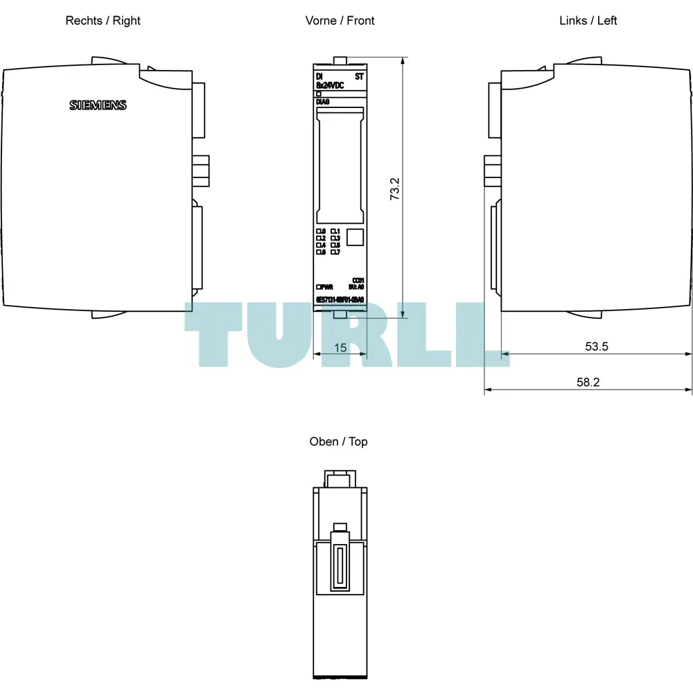
| Width | 15 mm |
| Height | 73 mm |
| Depth | 58 mm |
| Weight, approx. | 28 g |
| last modified: | 9/24/2021 |
| Product Condition | Brand New, New - Backlog, New - No Original Box, New - Original Box Opened, Used - Average, Used - Below Average, Used - Excellent, Used - Fairly Good, Used - Good, Used - Poor, Used - Very Good |
| Weight | 0.036 kg |
| Dimensions | 6.50 × 7.70 × 2.30 mm |
Request a quote for project quantities, discontinued or obsolete models, and pro-forma invoice / bank transfer orders. Our sourcing team responds fast.