SIEMENS
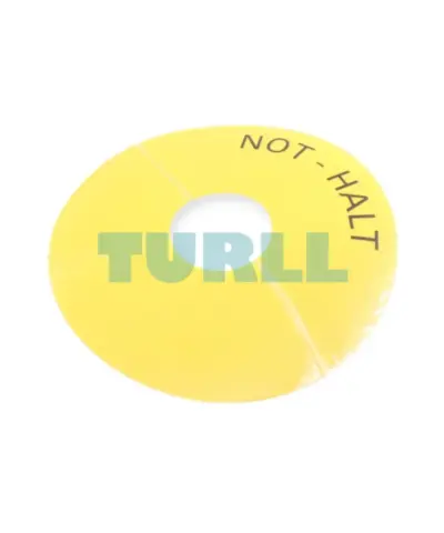
Siemens 3SU1900-0BC31-0AT0 Emergency Stop Backing Plate, Yellow, Self-Adhesive, 75mm Original Brand New
3SU1900-0BC31-0AT0
Original price was: $5.84.$2.36Current price is: $2.36.
In stock
SIEMENS
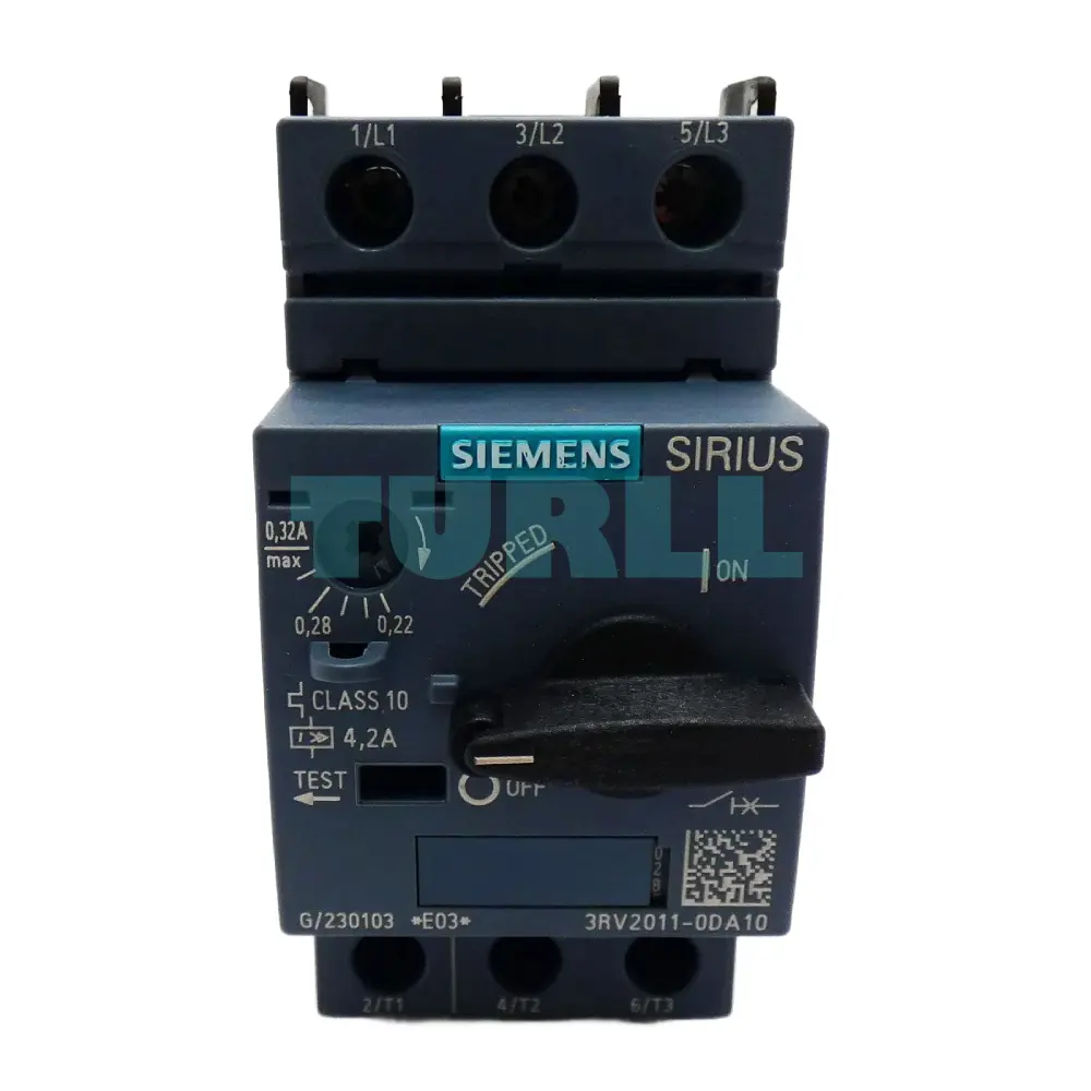
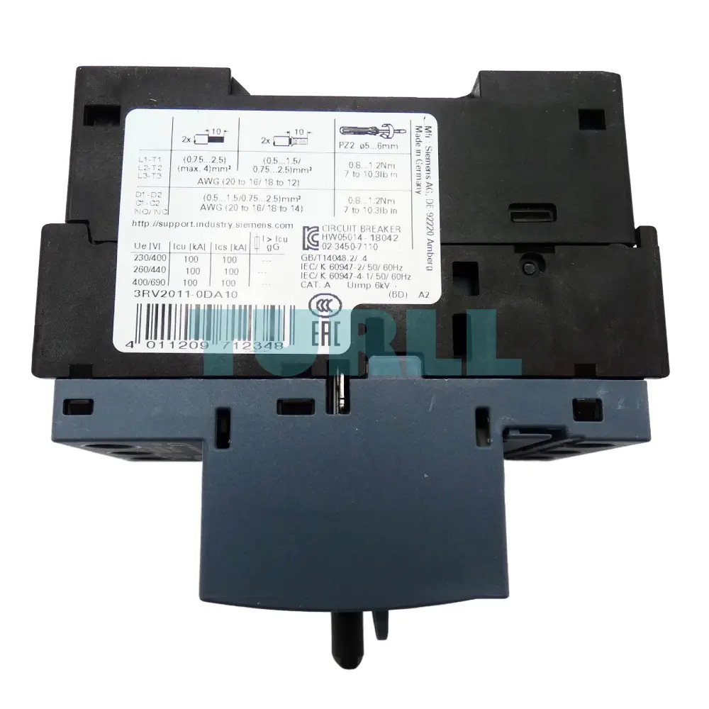
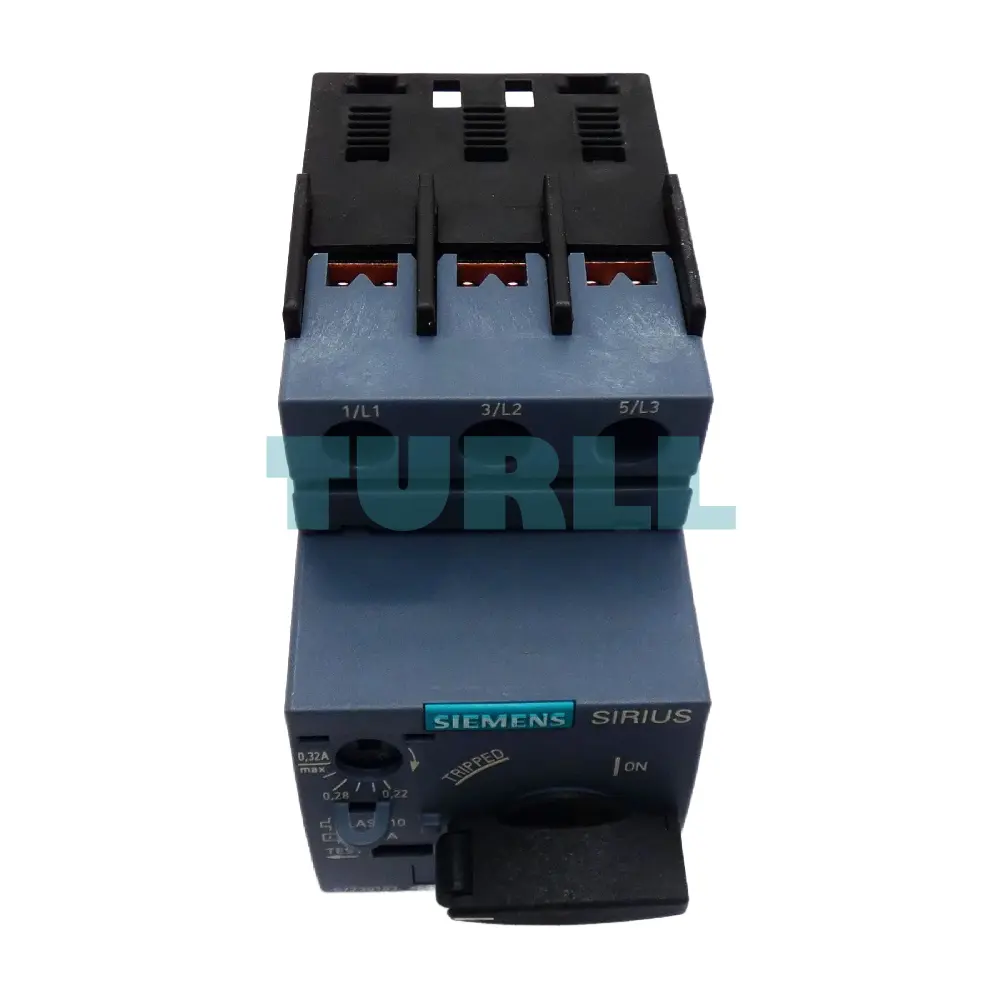
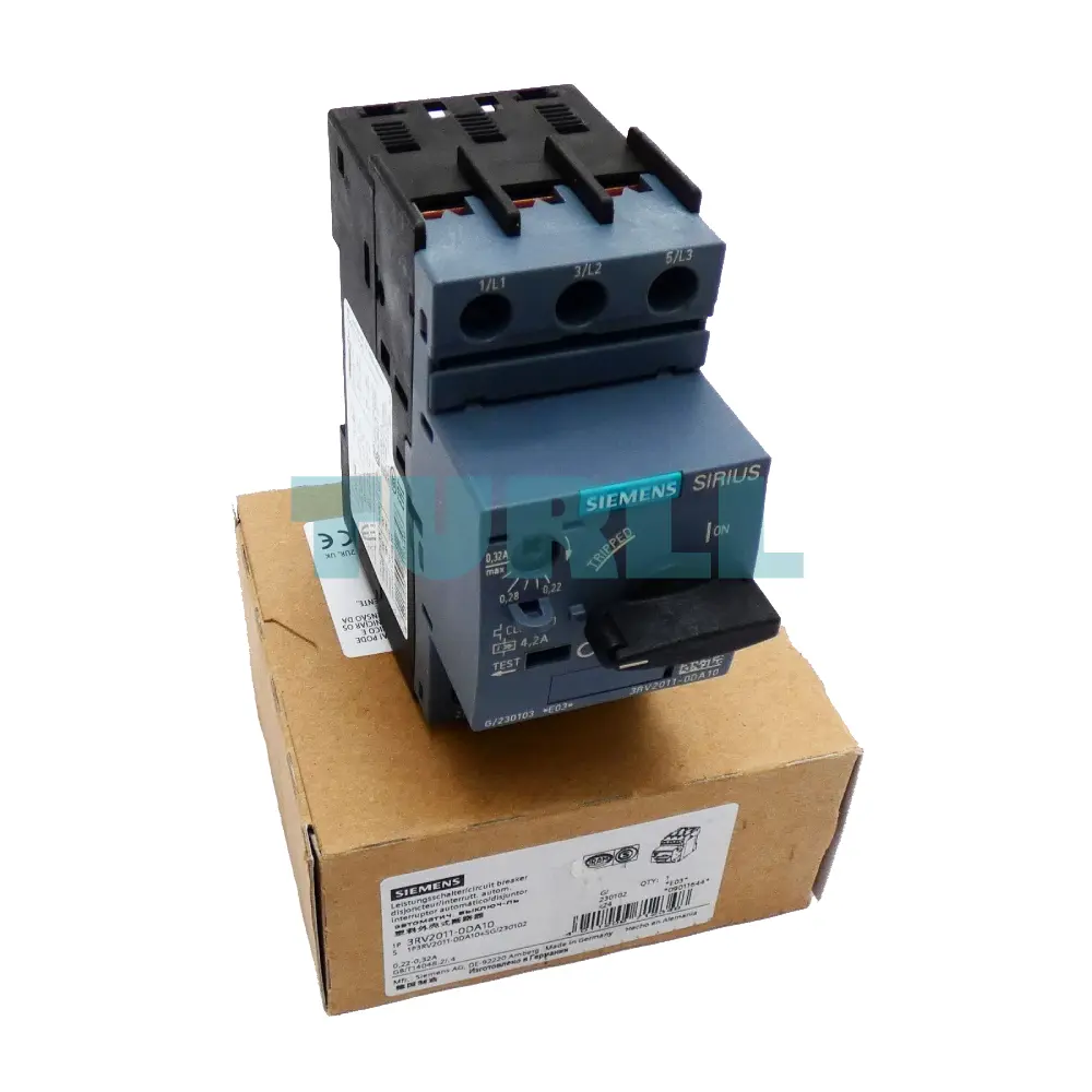
Circuit breaker size S00 for motor protection, CLASS 10. Features an adjustable A-release of 0.22…0.32 A and a fixed N-release of 4.2 A. This compact unit utilizes reliable screw terminals and offers standard switching capacity for efficient motor control and protection.
The Siemens 3RV2011-0DA10 is a high-quality motor protection circuit breaker designed for reliable protection of small motors and electrical equipment. With a CLASS 10 A-release, it ensures precise overload protection, and its 0.22–0.32 A N-release provides sensitive tripping for neutral currents. The S00 size compact design makes it ideal for industrial panels, while the standard switching capacity guarantees safe operation under normal and fault conditions. Featuring screw terminals, installation is secure and straightforward.
This circuit breaker is perfect for ensuring the safety and longevity of your electrical motors while maintaining compliance with industrial standards.
Reliable Motor Protection: Safeguards small motors from overload and short circuits.
Compact Design: S00 size fits easily into control panels with limited space.
Precision Tripping: CLASS 10 A-release and N-release 0.22–0.32 A ensure accurate protection.
Easy Installation: Screw terminals simplify wiring and maintenance.
High Switching Capacity: Standard switching capacity supports industrial applications.
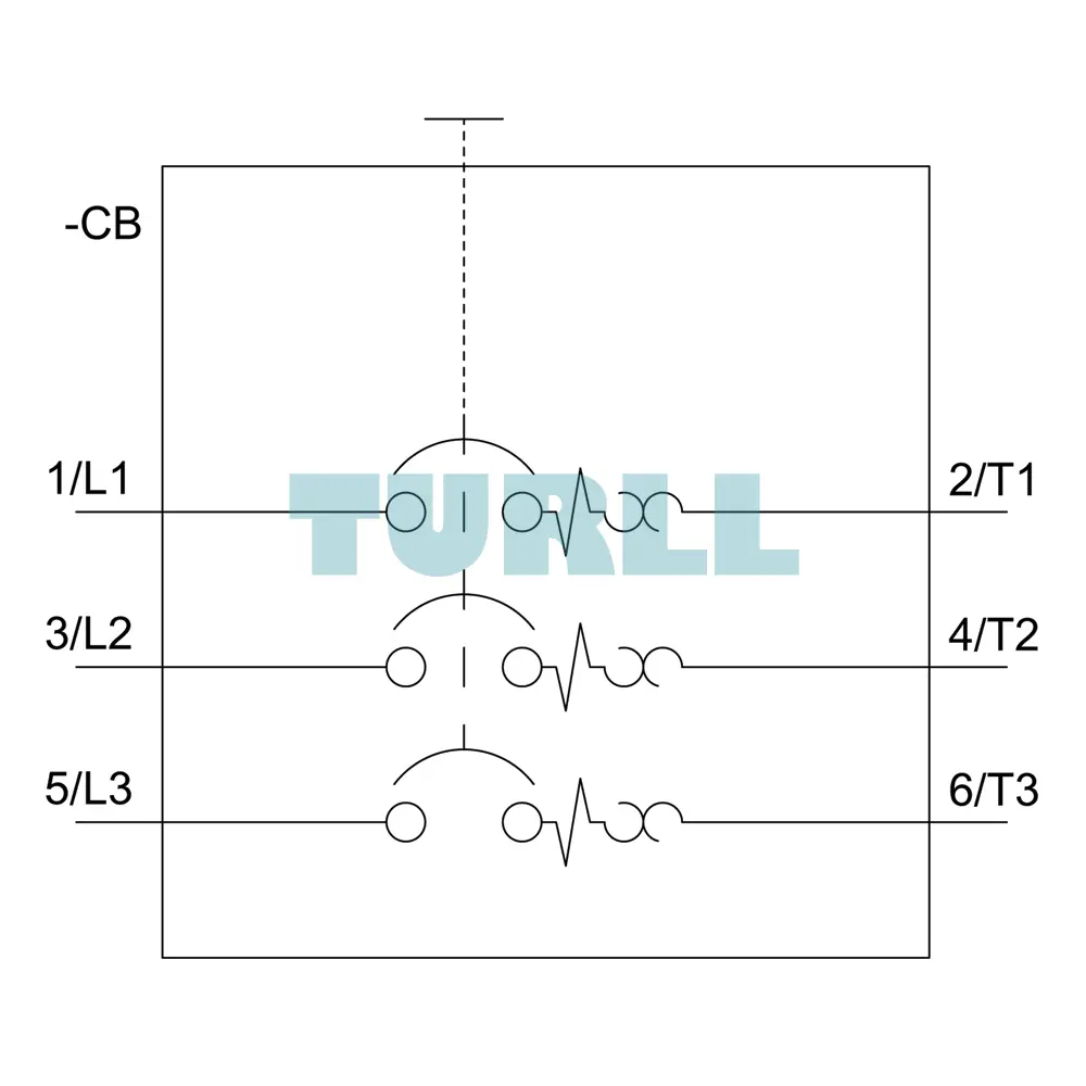
The Siemens 3RV2011-0DA10 functions as a motor starter protector, combining the features of a disconnect switch, a short-circuit protection device, and an overload relay into a single compact unit.
Motor Protection: It safeguards three-phase and single-phase AC motors.
Switching: It can be used for manual, local ON/OFF switching of motors.
Application Areas: Commonly used in machinery, HVAC systems, pumping stations, conveyor systems, and various other industrial automation and control applications.
Visit 3RV2011-0DA10 for more detail info
For more our products visit turll
| SKU / Model | 3RV2011-0DA10 |
|---|---|
| Brand | SIEMENS |
| product brand name | SIRIUS |
| product designation | Circuit breaker |
| design of the product | For motor protection |
| product type designation | 3RV2 |
| size of the circuit-breaker | S00 |
| size of contactor can be combined company-specific | S00, S0 |
| product extension auxiliary switch | Yes |
| power loss [W] for rated value of the current | - |
| ● at AC in hot operating state | 5.5 W |
| ● at AC in hot operating state per pole | 1.8 W |
| insulation voltage with degree of pollution 3 at AC rated value | 690 V |
| surge voltage resistance rated value | 6 kV |
| maximum permissible voltage for safe isolation in networks with grounded star point | - |
| ● between main and auxiliary circuit | 400 V |
| shock resistance acc. to IEC 60068-2-27 | 25g / 11 ms |
| mechanical service life (switching cycles) | - |
| ● of the main contacts typical | 100 000 |
| ● of auxiliary contacts typical | 100 000 |
| electrical endurance (switching cycles) typical | 100 000 |
| type of protection according to ATEX directive 2014/34/EU | Ex II (2) GD |
| certificate of suitability according to ATEX directive 2014/34/EU | DMT 02 ATEX F 001 |
| reference code acc. to IEC 81346-2 | Q |
| installation altitude at height above sea level maximum | 2 000 m |
| ambient temperature | - |
| ● during operation | -20 ... +60 °C |
| ● during storage | -50 ... +80 °C |
| ● during transport | -50 ... +80 °C |
| temperature compensation | -20 ... +60 °C |
| relative humidity during operation | 10 ... 95 % |
| number of poles for main current circuit | 3 |
| adjustable current response value current of the current-dependent overload release | 0.22 ... 0.32 A |
| operating voltage | - |
| ● rated value | 20 ... 690 V |
| ● at AC-3 rated value maximum | 690 V |
| operating frequency rated value | 50 ... 60 Hz |
| operational current rated value | 0.32 A |
| operational current at AC-3 at 400 V rated value | 0.32 A |
| operating power at AC-3 | - |
| ● at 230 V rated value | 0 kW |
| operating frequency at AC-3 maximum | 15 1/h |
| number of NC contacts for auxiliary contacts | 0 |
| number of NO contacts for auxiliary contacts | 0 |
| number of CO contacts for auxiliary contacts | 0 |
| product function | - |
| ● ground fault detection | No |
| ● phase failure detection | Yes |
| trip class | CLASS 10 |
| design of the overload release | thermal |
| breaking capacity operating short-circuit current (Ics) at AC | - |
| ● at 240 V rated value | 100 kA |
| ● at 400 V rated value | 100 kA |
| ● at 500 V rated value | 100 kA |
| ● at 690 V rated value | 100 kA |
| breaking capacity maximum short-circuit current (Icu) | - |
| ● at AC at 240 V rated value | 100 kA |
| ● at AC at 400 V rated value | 100 kA |
| ● at AC at 500 V rated value | 100 kA |
| ● at AC at 690 V rated value | 100 kA |
| response value current of instantaneous short-circuit trip unit | 4.2 A |
| full-load current (FLA) for 3-phase AC motor | - |
| ● at 480 V rated value | 0.32 A |
| ● at 600 V rated value | 0.32 A |
| product function short circuit protection | Yes |
| design of the short-circuit trip | magnetic |
| mounting position | any |
| fastening method | screw and snap-on mounting onto 35 mm standard mounting rail according to DIN EN 60715 |
| required spacing | - |
| ● for grounded parts at 400 V | - |
| ● for live parts at 400 V | - |
| ● for grounded parts at 500 V | - |
| ● for live parts at 500 V | - |
| ● for grounded parts at 690 V | - |
| ● for live parts at 690 V | - |
| — downwards | 50 mm |
| — upwards | 50 mm |
| — backwards | 0 mm |
| — at the side | 30 mm |
| — forwards | 0 mm |
| product component removable terminal for auxiliary and control circuit | No |
| type of electrical connection | - |
| ● for main current circuit | screw-type terminals |
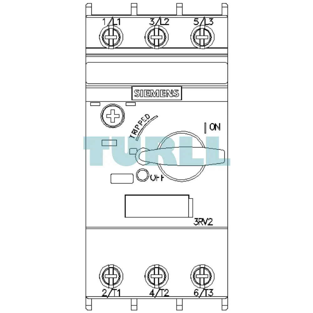
| arrangement of electrical connectors for main current circuit | Top and bottom |
| type of connectable conductor cross-sections | - |
| — solid or stranded | 2x (0,75 ... 2,5 mm²), 2x 4 mm² |
| — finely stranded with core end processing | 2x (0.5 ... 1.5 mm²), 2x (0.75 ... 2.5 mm²) |
| ● at AWG cables for main contacts | 2x (18 ... 14), 2x 12 |
| tightening torque | - |
| ● for main contacts with screw-type terminals | 0.8 ... 1.2 N·m |
| design of screwdriver shaft | Diameter 5 to 6 mm |
| size of the screwdriver tip | Pozidriv 2 |
| design of the thread of the connection screw | - |
| ● for main contacts | M3 |
| B10 value | - |
| proportion of dangerous failures | - |
| ● with high demand rate acc. to SN 31920 | 50 % |
| failure rate [FIT] | - |
| ● with low demand rate acc. to SN 31920 | 50 FIT |
| T1 value for proof test interval or service life acc. to IEC 61508 | 10 y |
| protection class IP on the front acc. to IEC 60529 | IP20 |
| touch protection on the front acc. to IEC 60529 | finger-safe, for vertical contact from the front |
| display version for switching status | Handle |
| For use in hazardous locations | Test Certificates Declaration of Conformity |
| last modified: | 11/16/2021 |
| Weight | 0.293 kg |
| Dimensions | 49.00 × 102.00 × 102.00 mm |
Request a quote for project quantities, discontinued or obsolete models, and pro-forma invoice / bank transfer orders. Our sourcing team responds fast.