SIEMENS
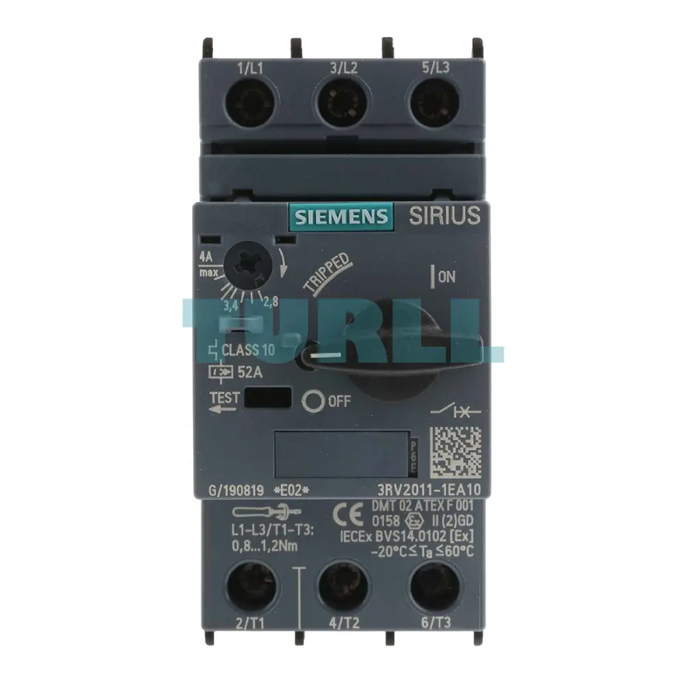
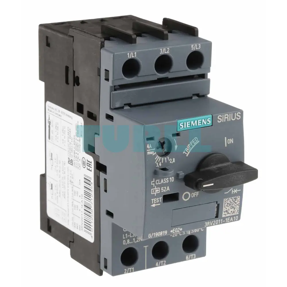
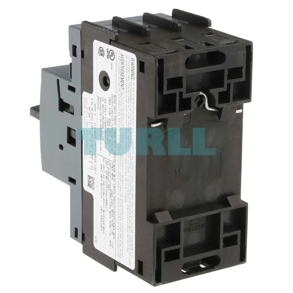
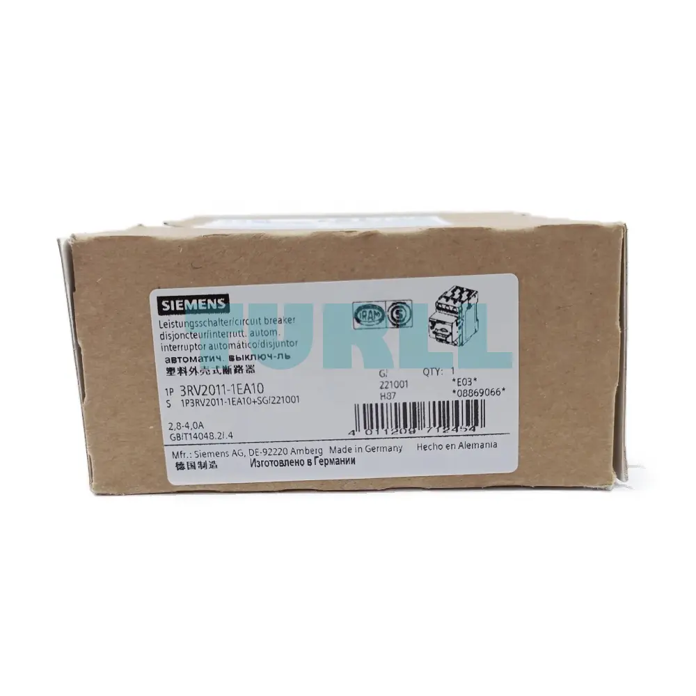
Siemens 3RV2011-1EA10 SIRIUS Motor Starter Protector, Size S00, 2.8-4A Original Brand New
SIRIUS size S00 circuit breaker designed specifically for motor protection. Featuring a CLASS 10 thermal overload release (2.8 to 4 A) and a 52 A instantaneous magnetic release, this unit ensures maximum safety for your industrial motors via a reliable screw terminal connection.
- ConditionOriginal Brand New
- Warranty12 months
- Genuine Products
- Up to 1-Year Warranty
- Global Shipping
- Secure Payment
- PI / Bank Transfer Available
- Bulk Quote Support
Description
Overview of the Siemens 3RV2011-1EA10
The Siemens 3RV2011-1EA10 is a centerpiece of the SIRIUS modular system, engineered to provide high-performance protection for three-phase motors up to 1.5 kW at 400 V. As a "Size S00" component, it boasts a remarkably compact footprint, making it ideal for space-constrained control cabinets and decentralized automation architectures.
This motor starter protector (MSP) is built to handle the rigors of industrial environments. It functions as a current-limiting circuit breaker for motor protection, ensuring that downstream equipment is shielded from the catastrophic effects of short circuits and thermal overloads. With its rugged design and Siemens’ world-renowned engineering, the 3RV2011-1EA10 offers a long service life and high operational reliability.
Key Benefit
-
Compact Modular Design: Part of the SIRIUS S00 family, allowing for seamless integration with contactors and overload relays using link modules, saving significant wiring time and rail space.
-
Global Compliance: Fully certified with international standards (IEC, UL, CSA), making it suitable for global export and diverse industrial applications.
-
Enhanced Safety: Provides reliable disconnection in the event of a fault, protecting both personnel and expensive machinery.
-
Easy Configuration: The adjustable bimetal heaters allow for precise setting of the motor’s rated current (2.8 to 4 A), ensuring the protection is perfectly tuned to your specific motor.
-
Durability: Designed for high switching frequency and a high degree of mechanical endurance.
Function
The primary function of the Siemens 3RV2011-1EA10 is to monitor and protect electrical loads through two distinct mechanisms:
-
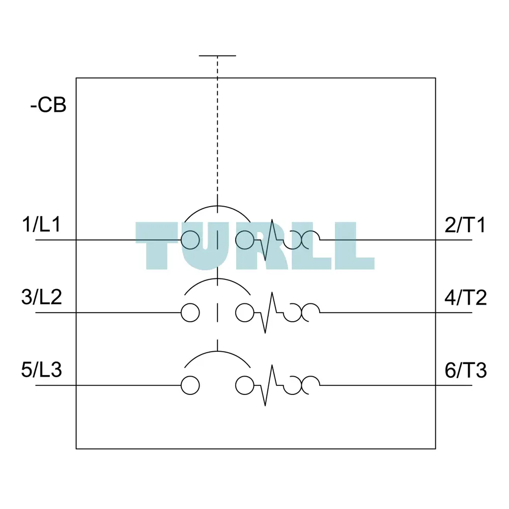
Thermal Overload Protection (CLASS 10): The adjustable thermal release (2.8...4 A) utilizes a bimetal strip that trips the breaker if the current stays above the set threshold for a duration defined by the Class 10 curve. This prevents the motor windings from overheating.
-
Short-Circuit Protection (N-Release): A fixed magnetic instantaneous release (set at 52 A) responds immediately to high-level faults, clearing short circuits in milliseconds to prevent fire and hardware destruction.
-
Phase Failure Sensitivity: The device is sensitive to phase loss, providing an extra layer of protection for three-phase motors that could otherwise burn out if one phase is dropped.
Industrial Application
The versatility of the 3RV2011-1EA10 makes it a staple in various sectors:
-
Manufacturing: Used in conveyor belts, small pumps, and fan motors where precise motor protection is required.
-
HVAC Systems: Ideal for protecting blower motors and circulation pumps in commercial climate control units.
-
Machine Building: Frequently used as a main switch or emergency-stop switch in small-to-medium machinery control panels.
-
Water Treatment: Protecting dosing pumps and agitators from stall conditions or electrical faults.
Installation and Maintenance
Thanks to the screw terminal system, installation is straightforward and ensures a gas-tight, vibration-resistant connection. The device can be mounted on a standard 35mm DIN rail. Maintenance is minimal; however, it is recommended to periodically test the trip mechanism using the integrated test slider to ensure the internal linkage remains free and responsive.
Visit 3RV2011-1EA10 for more detail info
For more our products visit turll
Download
Specifications
| SKU / Model | 3RV2011-1EA10 |
|---|---|
| Brand | SIEMENS |
| product brand name | SIRIUS |
| product designation | Circuit breaker |
| design of the product | For motor protection |
| product type designation | 3RV2 |
| size of the circuit-breaker | S00 |
| size of contactor can be combined company-specific | S00, S0 |
| product extension auxiliary switch | Yes |
| power loss [W] for rated value of the current | - |
| ● at AC in hot operating state | 7.25 W |
| ● at AC in hot operating state per pole | 2.4 W |
| insulation voltage with degree of pollution 3 at AC rated value | 690 V |
| surge voltage resistance rated value | 6 kV |
| maximum permissible voltage for safe isolation in networks with grounded star point | - |
| ● between main and auxiliary circuit | 400 V |
| shock resistance acc. to IEC 60068-2-27 | 25g / 11 ms |
| mechanical service life (switching cycles) | - |
| ● of the main contacts typical | 100 000 |
| ● of auxiliary contacts typical | 100 000 |
| electrical endurance (switching cycles) typical | 100 000 |
| type of protection according to ATEX directive 2014/34/EU | Ex II (2) GD |
| certificate of suitability according to ATEX directive 2014/34/EU | DMT 02 ATEX F 001 |
| reference code acc. to IEC 81346-2 | Q |
| installation altitude at height above sea level maximum | 2 000 m |
| ambient temperature | - |
| ● during operation | -20 ... +60 °C |
| ● during storage | -50 ... +80 °C |
| ● during transport | -50 ... +80 °C |
| temperature compensation | -20 ... +60 °C |
| relative humidity during operation | 10 ... 95 % |
| number of poles for main current circuit | 3 |
| adjustable current response value current of the current-dependent overload release | 2.8 ... 4 A |
| operating voltage | - |
| ● rated value | 20 ... 690 V |
| ● at AC-3 rated value maximum | 690 V |
| operating frequency rated value | 50 ... 60 Hz |
| operational current rated value | 4 A |
| operational current at AC-3 at 400 V rated value | 4 A |
| operating power at AC-3 | - |
| ● at 230 V rated value | 0.8 kW |
| operating frequency at AC-3 maximum | 15 1/h |
| number of NC contacts for auxiliary contacts | 0 |
| number of NO contacts for auxiliary contacts | 0 |
| number of CO contacts for auxiliary contacts | 0 |
| product function | - |
| ● ground fault detection | No |
| ● phase failure detection | Yes |
| trip class | CLASS 10 |
| design of the overload release | thermal |
| breaking capacity operating short-circuit current (Ics) at AC | - |
| ● at 240 V rated value | 100 kA |
| ● at 400 V rated value | 100 kA |
| ● at 500 V rated value | 100 kA |
| ● at 690 V rated value | 4 kA |
| breaking capacity maximum short-circuit current (Icu) | - |
| ● at AC at 240 V rated value | 100 kA |
| ● at AC at 400 V rated value | 100 kA |
| ● at AC at 500 V rated value | 100 kA |
| ● at AC at 690 V rated value | 6 kA |
| response value current of instantaneous short-circuit trip unit | 52 A |
| full-load current (FLA) for 3-phase AC motor | - |
| ● at 480 V rated value | 4 A |
| ● at 600 V rated value | 4 A |
| yielded mechanical performance [hp] | - |
| ● for single-phase AC motor | - |
| — at 110/120 V rated value | 0.13 hp |
| — at 230 V rated value | 0.33 hp |
| ● for 3-phase AC motor | - |
| — at 200/208 V rated value | 0.8 hp |
| — at 220/230 V rated value | 0.75 hp |
| — at 460/480 V rated value | 2 hp |
| — at 575/600 V rated value | 3 hp |
| product function short circuit protection | Yes |
| design of the short-circuit trip | magnetic |
| design of the fuse link for IT network for short-circuit protection of the main circuit | - |
| ● at 400 V | gL/gG 32 A |
| ● at 500 V | gL/gG 32 A |
| ● at 690 V | gL/gG 25 A |
| mounting position | any |
| fastening method | screw and snap-on mounting onto 35 mm standard mounting rail according to DIN EN 60715 |
| required spacing | - |
| ● for grounded parts at 400 V | - |
| ● for live parts at 400 V | - |
| ● for grounded parts at 500 V | - |
| ● for live parts at 500 V | - |
| ● for grounded parts at 690 V | - |
| ● for live parts at 690 V | - |
| — downwards | 50 mm |
| — upwards | 50 mm |
| — backwards | 0 mm |
| — at the side | 30 mm |
| — forwards | 0 mm |
| product component removable terminal for auxiliary and control circuit | No |
| type of electrical connection | - |
| ● for main current circuit | screw-type terminals |
| arrangement of electrical connectors for main current circuit | Top and bottom |
| type of connectable conductor cross-sections | - |
| — solid or stranded | 2x (0,75 ... 2,5 mm²), 2x 4 mm² |
| — finely stranded with core end processing | 2x (0.5 ... 1.5 mm²), 2x (0.75 ... 2.5 mm²) |
| ● at AWG cables for main contacts | 2x (18 ... 14), 2x 12 |
| tightening torque | - |
| ● for main contacts with screw-type terminals | 0.8 ... 1.2 N·m |
| design of screwdriver shaft | Diameter 5 to 6 mm |
| size of the screwdriver tip | Pozidriv 2 |
| design of the thread of the connection screw | - |
| ● for main contacts | M3 |
| B10 value | - |
| proportion of dangerous failures | - |
| ● with high demand rate acc. to SN 31920 | 50 % |
| failure rate [FIT] | - |
| ● with low demand rate acc. to SN 31920 | 50 FIT |
| T1 value for proof test interval or service life acc. to IEC 61508 | 10 y |
| protection class IP on the front acc. to IEC 60529 | IP20 |
| touch protection on the front acc. to IEC 60529 | finger-safe, for vertical contact from the front |
| display version for switching status | Handle |
| For use in hazardous locations | Test Certificates Declaration of Conformity |
| last modified: | 11/16/2021 |
| Weight | 0.345 kg |
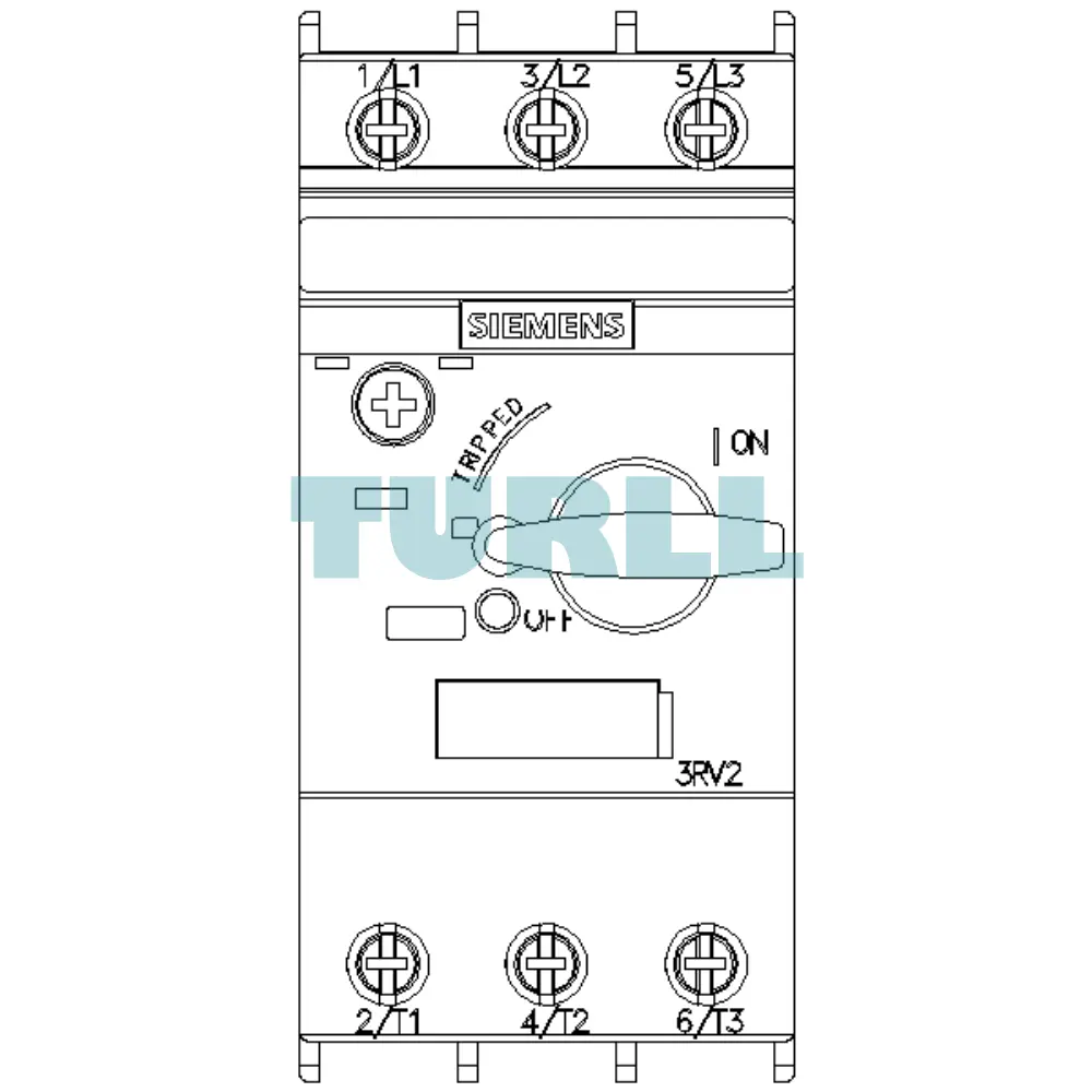
| Dimensions | 49.00 × 102.00 × 102.00 mm |
Need bulk pricing or a hard-to-find part?
Request a quote for project quantities, discontinued or obsolete models, and pro-forma invoice / bank transfer orders. Our sourcing team responds fast.