SIEMENS
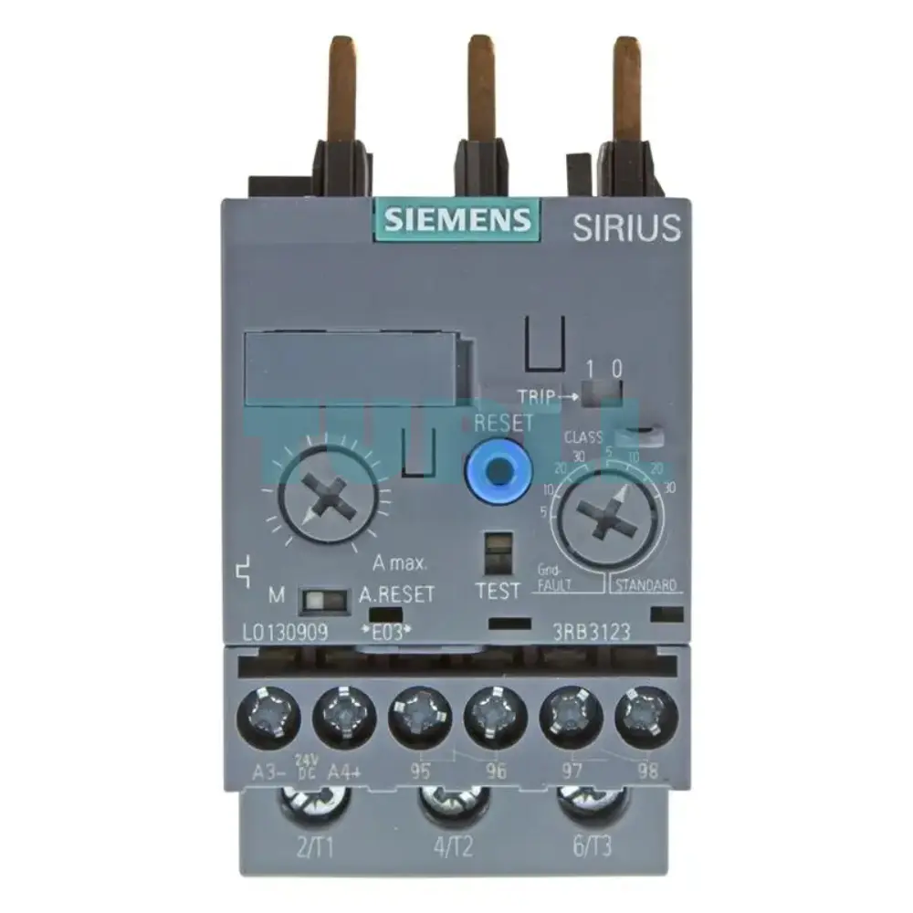
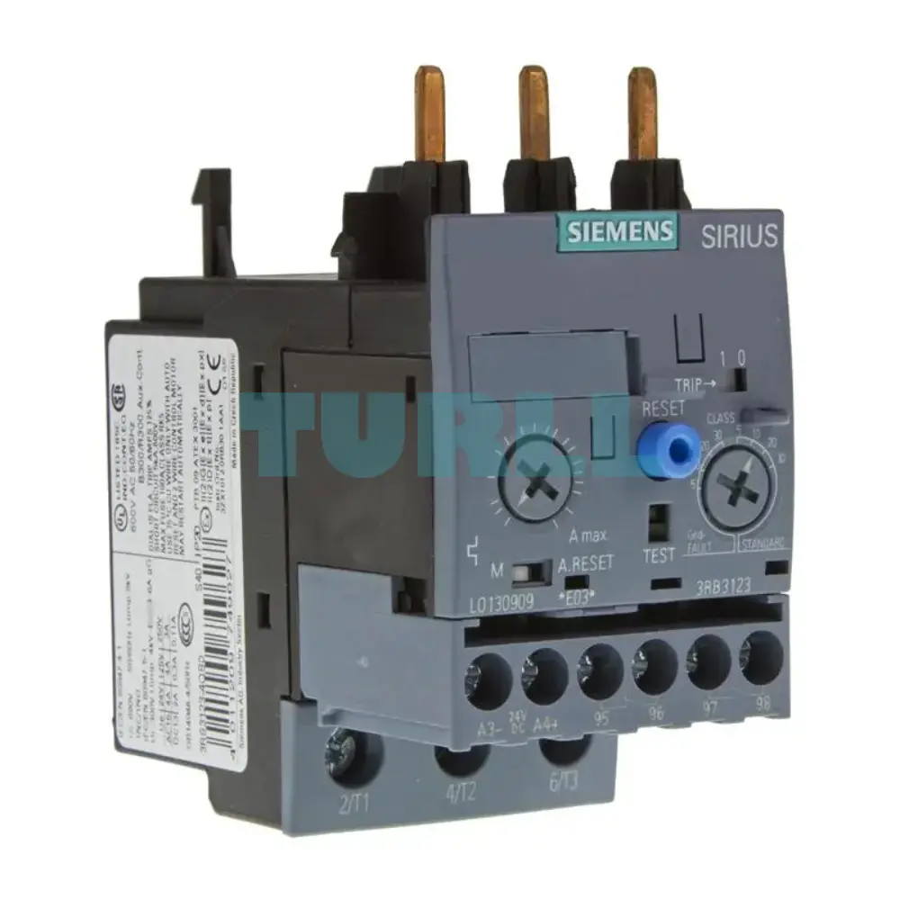
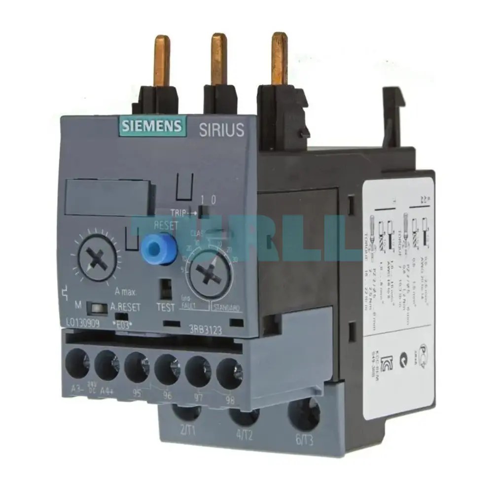
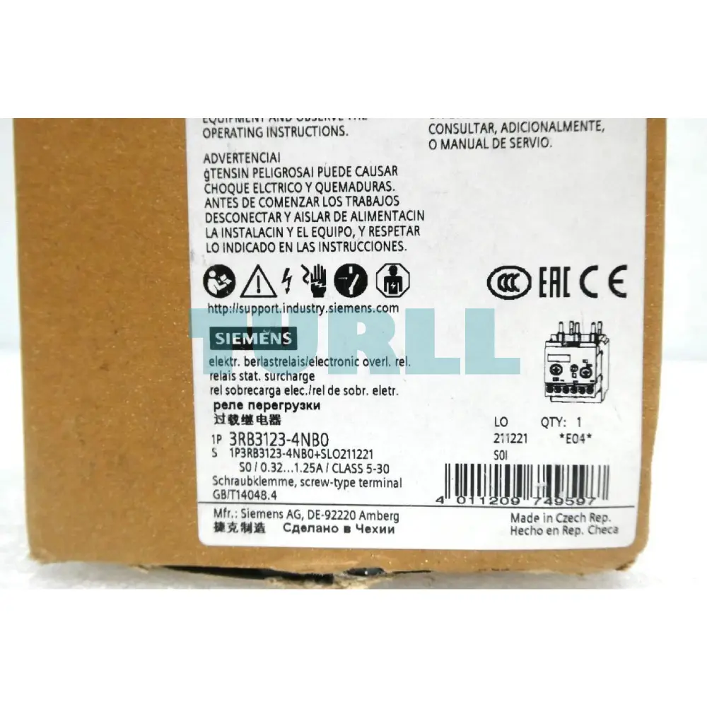
Siemens 3RB3123-4NB0 Electronic Overload Relay 0.32–1.25A for Motor Protection, Size S0 Original Brand New
Protect your motors with the Siemens 3RB3123-4NB0. An electronic overload relay for Size S0, featuring a 0.32-1.25A range, adjustable trip classes (5-30), and integrated ground fault detection. Reliable screw-connection technology for industrial automation.
- ConditionOriginal Brand New
- Warranty12 months
Backorder available · Factory lead time 2–3 weeks.
- Genuine Products
- Up to 1-Year Warranty
- Global Shipping
- Secure Payment
- PI / Bank Transfer Available
- Bulk Quote Support
Description
Overview
The Siemens 3RB3123-4NB0 Electronic Overload Relay is a high-performance motor protection device designed to safeguard electric motors from overloads, phase failures, and internal ground faults. Engineered with Siemens’ advanced electronic protection technology, this relay ensures reliable motor operation while minimizing downtime and maintenance costs.
This overload relay supports a current range of 0.32 to 1.25 A, making it ideal for low-current motor applications. It is built in Size S0 and optimized for contactor mounting, allowing seamless integration into motor control systems. The relay features adjustable tripping classes from Class 5 to Class 30, offering flexibility to suit different motor startup conditions and load requirements.
With manual and automatic reset options, screw-type terminals for both main and auxiliary circuits, and internal ground fault detection, the Siemens 3RB3123-4NB0 provides comprehensive protection, accuracy, and long-term reliability in industrial environments.
Key Benefit
1. Advanced Motor Protection
The electronic sensing technology ensures precise current monitoring, protecting motors against overload, phase imbalance, and ground faults more effectively than traditional thermal relays.
2. Adjustable Tripping Class (5–30)
This feature allows users to tailor the relay response to various motor types, including standard-duty and heavy-duty applications.
3. Compact and Space-Saving Design
Size S0 construction enables easy installation in compact control panels without compromising performance.
4. Flexible Reset Options
Supports both manual and automatic reset, providing operational flexibility and improved system uptime.
5. Internal Ground Fault Detection
Integrated ground fault monitoring adds an extra layer of safety, helping to prevent motor damage and electrical hazards.
Function
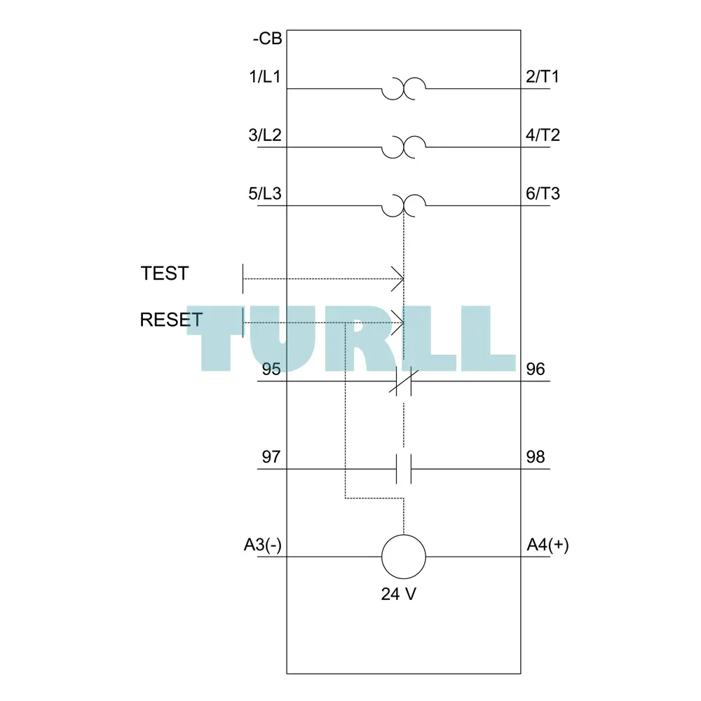
The Siemens 3RB3123-4NB0 operates by measuring the motor current via integrated current transformers. The electronic evaluation system processes these values and compares them to the set current.
-
Overload Protection: Triggers if the current exceeds the set threshold for a duration determined by the selected trip class.
-
Phase Failure Protection: Rapidly detects the loss of a phase to prevent unbalanced heating of the motor windings.
-
Ground Fault Detection: Monitors for current leakage to earth, providing an extra layer of protection for the motor and cabling.
-
Reset Modes: Features a flexible Manual/Automatic/Remote Reset selector, allowing for customized recovery protocols after a fault occurs.
Application
The Siemens 3RB3123-4NB0 Overload Relay is suitable for a wide range of industrial and commercial motor protection applications, including:
-
Industrial motor control panels
-
Conveyor systems
-
Pumps and compressors
-
HVAC systems
-
Packaging machinery
-
Automation and control systems
-
Manufacturing and processing plants
This relay is especially recommended for applications where precise protection, reliability, and compact installation are essential.
Technical Highlight
-
Current Range: 0.32 – 1.25 A
-
Relay Type: Electronic overload relay
-
Size: S0
-
Tripping Class: Class 5 to Class 30
-
Mounting Type: Contactor mounting
-
Main Circuit Connection: Screw terminals
-
Auxiliary Circuit Connection: Screw terminals
-
Reset Type: Manual / Automatic
-
Protection Features: Overload, phase failure, internal ground fault detection
Installation and Maintenance
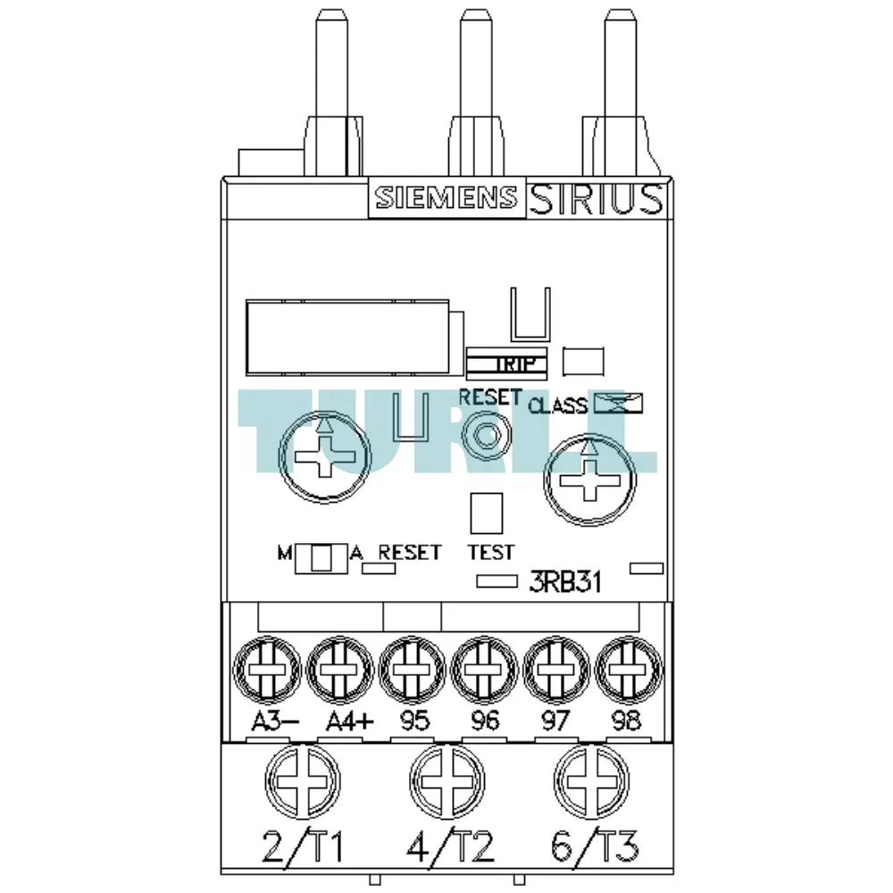
Mounting the 3RB3123-4NB0 is straightforward. It features screw terminals for both the main circuit and the auxiliary circuit. The relay is designed for direct mounting onto S0 contactors, but standalone installation is also possible using separate mounting brackets. Maintenance is minimal; however, periodic testing of the "Test/Stop" function is recommended to ensure the auxiliary contacts are functioning correctly.
Visit 3RB3123-4NB0 for more detail info
For more our products visit turll
Download
Specifications
| SKU / Model | 3RB3123-4NB0 |
|---|---|
| Brand | SIEMENS |
| product brand name | SIRIUS |
| product designation | solid-state overload relay |
| product type designation | 3RB3 |
| size of overload relay | S0 |
| size of contactor can be combined company-specific | S0 |
| power loss [W] for rated value of the current at AC in hot operating state | 0.1 W |
| ● per pole | 0.03 W |
| insulation voltage with degree of pollution 3 at AC rated value | 690 V |
| surge voltage resistance rated value | 6 kV |
| maximum permissible voltage for safe isolation in networks with grounded star point | - |
| ● between auxiliary and auxiliary circuit | 300 V |
| ● between main and auxiliary circuit | 690 V |
| shock resistance | 15g / 11 ms |
| ● acc. to IEC 60068-2-27 | 15g / 11 ms; Signaling contact 97 / 98 in position "Tripped": 9g / 11 ms |
| vibration resistance | 1-6 Hz, 15 mm; 6-500 Hz, 20 m/s²; 10 cycles |
| thermal current | 1.25 A |
| type of protection according to ATEX directive 2014/34/EU | Ex II (2) G [Ex e] [Ex d] [Ex px] ; Ex II (2) D [Ex t] [Ex p] |
| certificate of suitability according to ATEX directive 2014/34/EU | PTB 09 ATEX 3001 |
| reference code acc. to IEC 81346-2 | F |
| installation altitude at height above sea level maximum | 2 000 m |
| ambient temperature | - |
| ● during operation | -25 ... +60 °C |
| ● during storage | -40 ... +80 °C |
| ● during transport | -40 ... +80 °C |
| temperature compensation | -25 ... +60 °C |
| relative humidity during operation | 10 ... 95 % |
| number of poles for main current circuit | 3 |
| adjustable current response value current of the current-dependent overload release | 0.32 ... 1.25 A |
| operating voltage | - |
| ● rated value | 690 V |
| ● for remote-reset function at DC | 24 V |
| ● at AC-3 rated value maximum | 690 V |
| operating frequency rated value | 50 ... 60 Hz |
| operational current rated value | 1.25 A |
| operating power | - |
| ● for 3-phase motors at 400 V at 50 Hz | 0.12 ... 0.37 kW |
| ● for AC motors at 500 V at 50 Hz | 0.12 ... 0.55 kW |
| ● for AC motors at 690 V at 50 Hz | 0.18 ... 0.75 kW |
| design of the auxiliary switch | integrated |
| number of NC contacts for auxiliary contacts | 1 |
| number of NO contacts for auxiliary contacts | 1 |
| ● note | for message "tripped" |
| number of CO contacts for auxiliary contacts | 0 |
| operational current of auxiliary contacts at AC-15 | - |
| ● at 120 V | 4 A |
| ● at 230 V | 3 A |
| operational current of auxiliary contacts at DC-13 | - |
| ● at 24 V | 2 A |
| ● at 60 V | 0.55 A |
| ● at 110 V | 0.3 A |
| ● at 125 V | 0.3 A |
| ● at 220 V | 0.11 A |
| trip class | CLASS 5E, 10E, 20E and 30E adjustable |
| design of the overload release | electronic |
| response value current of the grounding protection minimum | 0.75 x IMotor |
| response time of the grounding protection in settled state | 1 000 ms |
| operating range of the grounding protection relating to current set value | - |
| ● minimum | IMotor > lower current setting value |
| ● maximum | IMotor < upper current setting value x 3.5 |
| full-load current (FLA) for 3-phase AC motor | - |
| ● at 480 V rated value | 1.25 A |
| ● at 600 V rated value | 1.25 A |
| contact rating of auxiliary contacts according to UL | B600 / R300 |
| design of the fuse link | - |
| ● for short-circuit protection of the main circuit | - |
| — with type of coordination 1 required | gG: 35 A, RK5: 6 A |
| — with type of assignment 2 required | gG: 6 A |
| ● for short-circuit protection of the auxiliary switch required | fuse gG: 6 A |
| mounting position | any |
| fastening method | Contactor mounting |
| product component removable terminal for auxiliary and control circuit | Yes |
| type of electrical connection | - |
| ● for main current circuit | screw-type terminals |
| ● for auxiliary and control circuit | screw-type terminals |
| arrangement of electrical connectors for main current circuit | Top and bottom |
| — stranded | 2x 10 mm² |
| ● at AWG cables for main contacts | 1x (16 ... 8), 2x (16 ... 8) |
| type of connectable conductor cross-sections | - |
| ● for auxiliary contacts | - |
| — solid | 1x (0.5 ... 4 mm²), 2x (0.5 ... 2.5 mm²) |
| — solid or stranded | 1x (0,5 ... 4 mm²), 2x (0,5 ... 2,5 mm²) |
| — finely stranded with core end processing | 1x (0.5 ... 2.5 mm²), 2x (0.5 ... 1.5 mm²) |
| ● at AWG cables for auxiliary contacts | 1x (20 ... 14), 2x (20 ... 14) |
| tightening torque | - |
| ● for main contacts with screw-type terminals | 2 ... 2.5 N·m |
| ● for auxiliary contacts with screw-type terminals | 0.8 ... 1.2 N·m |
| design of screwdriver shaft | Diameter 5 to 6 mm |
| size of the screwdriver tip | Pozidriv PZ 2 |
| design of the thread of the connection screw | - |
| ● for main contacts | M4 |
| ● of the auxiliary and control contacts | M3 |
| protection class IP on the front acc. to IEC 60529 | IP20 |
| touch protection on the front acc. to IEC 60529 | finger-safe, for vertical contact from the front |
| type of voltage supply via input/output link master | No |
| conducted interference | - |
| ● due to burst acc. to IEC 61000-4-4 | 2 kV (power ports), 1 kV (signal ports) corresponds to degree of severity 3 |
| ● due to conductor-earth surge acc. to IEC 61000-4-5 | 2 kV (line to earth) corresponds to degree of severity 3 |
| ● due to conductor-conductor surge acc. to IEC 61000-4-5 | 1 kV (line to line) corresponds to degree of severity 3 |
| ● due to high-frequency radiation acc. to IEC 61000-4-6 | 10 V in frequency range 0.15 to 80 MHz, modulation 80 % AM with 1 kHz |
| field-based interference acc. to IEC 61000-4-3 | 10 V/m |
| electrostatic discharge acc. to IEC 61000-4-2 | 6 kV contact discharge / 8 kV air discharge |
| display version for switching status | Slide switch |
| last modified: | 12/15/2020 |
| Weight | 0.215 kg |
| Dimensions | 98.00 × 116.00 × 57.00 mm |
Need bulk pricing or a hard-to-find part?
Request a quote for project quantities, discontinued or obsolete models, and pro-forma invoice / bank transfer orders. Our sourcing team responds fast.