


3RT2526-1BF40 Siemens SIRIUS Power Contactor Original Brand New
$77.59
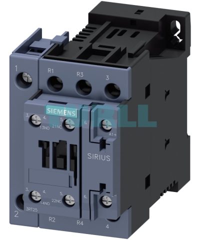
3RT2526-1BF40
Siemens power contactor, AC-3, 25 A, 11 kW / 400 V, 4-pole, 110 V DC, main contacts: 2 NO + 2 NC, auxiliary contacts: 1 NO + 1 NC, screw terminal, size: S0

[ez-toc]
Overview
Standards
IEC 60947‑1, IEC 60947‑4‑1, IEC 60947‑5‑1 (auxiliary switches)
Protection of the device connections against short circuit, overload, and overvoltage
All connections must generally be protected against overload and short circuits using suitable measures. Different constraints must be considered depending on the type of connection:
Short-circuit and overload protection of main connections
For information on the protection of a free-standing contactor, see the technical product data sheet.
For more information on device combinations such as contactor with overload relay or contactor with motor starter protector/circuit breaker as motor feeder, refer to
Short-circuit and overload protection of auxiliary connections
For information on the protection of auxiliary contacts, see the technical product data sheet.
Short-circuit and overload protection of control supply voltage or supply voltage connections
First of all, the relevant standards and regulations for configuring control panels and the parts and components installed in them must be taken into account, for example for cable dimensioning.
One possible protection for these circuits could be the selection of a suitable power supply, i.e. one with a current-limiting function. In the selection of the source and the connecting cable, the load characteristics of the contactor must be considered (short-time inrush current peaks for solid-state contactor operating mechanisms, switch-on power, holding power). The same applies to the selection of suitable protection devices.
If there are further switching elements in the circuit, such as the auxiliary contact system of an overload relay that operates the contactor, the short-circuit protection necessary for this must also be considered.
For further recommendations, e.g. the use of miniature or circuit breakers for equipment in control circuits, see Control panel tip – Selecting and dimensioning suitable power supplies quickly and reliably.
Protection against overvoltage at the control supply voltage connection
3RT25 contactors supplied without a coil circuit can be retrofitted with RC elements, varistors, diodes or diode assemblies (assembly of diode and Zener diode for short break times) for damping switching overvoltages in the coil and must be ordered separately as accessory, see Surge suppressors.
Note:
The break times of the contactor, the opening delay times of the NO contacts and the closing delay times of the NC contacts increase with damping.
For more information on how damping influences the time response, see the Equipment Manual.
Replacing solenoid coils or spare contacts
Solenoid coil or contact replacement is possible.
Fitting auxiliary contacts and mounting additional auxiliary switches
Equipment as supplied
The basic units 3RT252 to 3RT254 contain two integrated auxiliary contacts (1 NO + 1 NC).
Expansion possibilities
All basic units can be expanded using auxiliary switches; the permissible configuration must be observed.
For detailed information on fitting auxiliary switches for 3RT25 contactors, see Auxiliary switches, instantaneous → Overview.
Accessories
The accessories for the 3-pole 3RT2 contactors can also be used for the 4-pole versions, see Accessories and spare parts for SIRIUS 3RT2 contactors and SIRIUS 3RH2 contactor relays.
Application
The contactors are suitable for:
- For changing the polarity of hoisting gear motors
- For switching two separate loads
Note:
Single device for pole reversal; not suitable for reversing duty. 3RT25 contactors are not suitable for switching a load between two current sources.
3RT2526-1BF40
Siemens power contactor, AC-3, 25 A, 11 kW / 400 V, 4-pole, 110 V DC, main contacts: 2 NO + 2 NC, auxiliary contacts: 1 NO + 1 NC, screw terminal, size: S0
Visit 3RT2526-1BF40
For more our products visit turll.com
| Weight | 0.651 kg |
|---|---|
| Dimensions | 77.00 × 93.00 × 130.00 mm |
You must be logged in to post a review.
Reviews
There are no reviews yet.