SIEMENS
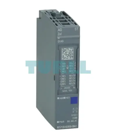
Siemens 6ES7135-6GB00-0BA1 SIMATIC ET 200SP, Analog Output Module, AQ 2xI Standard, 16 Bit Original Brand New
6ES7135-6GB00-0BA1
$272.85
On backorder
Factory lead time 2–3 weeks
SIEMENS
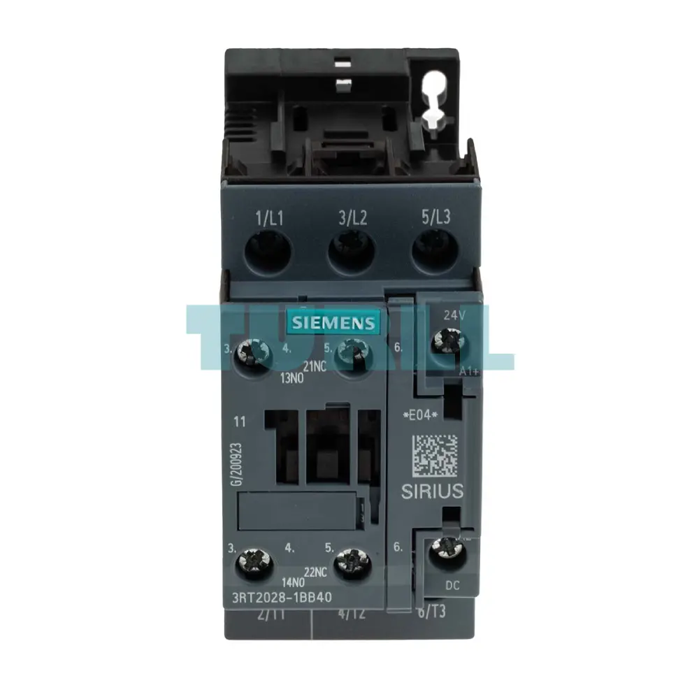
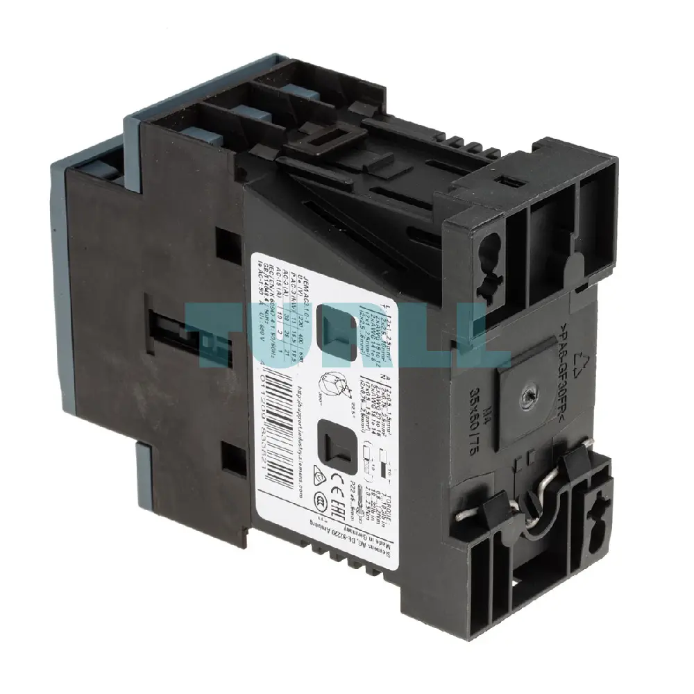
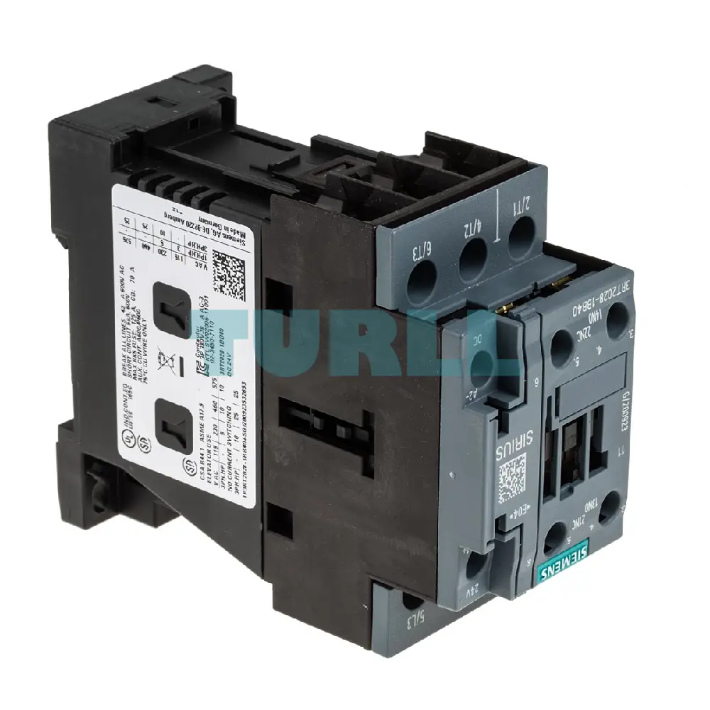
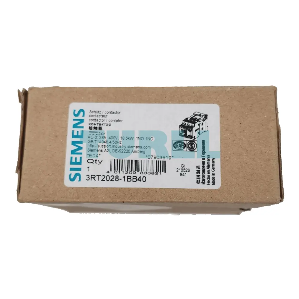
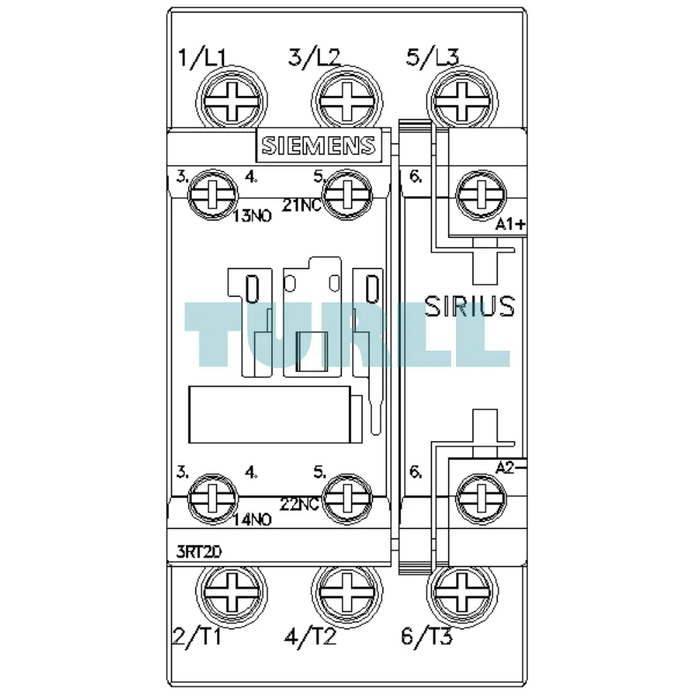
Siemens 3RT2028-1BB40 is a Size S0 power contactor rated at 38 A / 18.5 kW. It features a 24 V DC operating coil, 3-poles, and integrated 1 NO + 1 NC auxiliary contacts. Connectors are screw terminals. This SIRIUS component offers robust and reliable switching for industrial motor control applications.
The Siemens 3RT2028-1BB40 is a high-performance power contactor from the globally renowned SIRIUS series, designed for switching motors and general industrial loads. Built in size S0, it combines a compact footprint with robust switching capacity, making it an essential component for any modern control panel, motor control center, or automation application requiring reliable power control up to 18.5 kW / 400 V.
Reliable Performance: SIRIUS quality ensures long-term operational stability for critical industrial processes.
Direct PLC Integration: The 24 V DC coil simplifies integration, offering low-power switching and compatibility with standard automation systems.
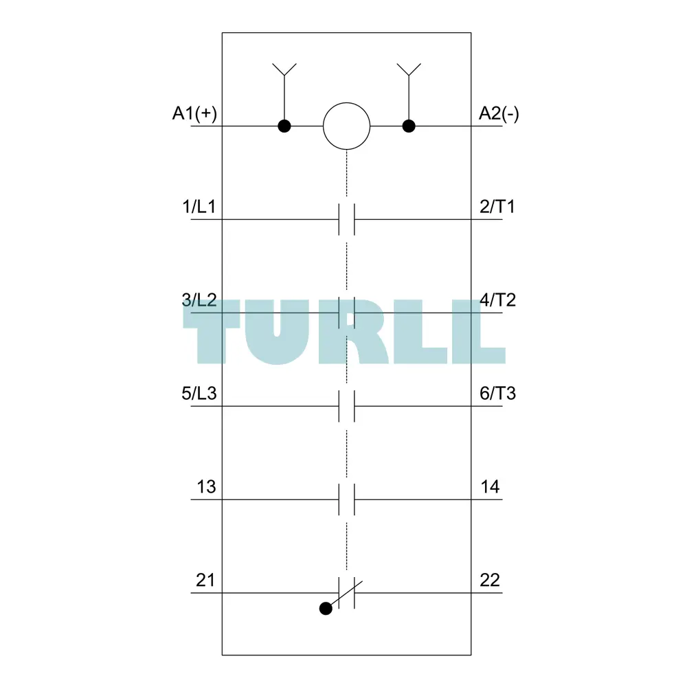
Versatile Auxiliary Contacts: The built-in 1 NO + 1 NC contacts provide immediate feedback on the contactor's status for interlocking, control, and signaling circuits without the need for additional modules.
Secure Connection: Robust screw terminals guarantee a strong, vibration-proof connection, minimizing downtime and maintenance.
Space Saving: The compact Size S0 design maximizes panel space efficiency.
Rated operational current: 38 A
Rated motor power: 18.5 kW at 400 V
Control voltage: 24 V DC
Poles: 3-pole
Auxiliary contacts: 1 Normally Open (NO) + 1 Normally Closed (NC)
Terminal type: Screw terminal
Size: S0
Application category: AC-3e / AC-3
The 3RT2028-1BB40 contactor is ideal for:
Motor control and protection (e.g., pumps, fans, conveyors)
Switching resistive loads (e.g., heating elements)
Controlling lighting and general-purpose industrial loads
Use in motor starters (Direct-on-line, Reversing)
Visit 3RT2028-1BB40 for more detail info
For more our products visit turll
| SKU / Model | 3RT2028-1BB40 |
|---|---|
| Brand | SIEMENS |
| product brand name | SIRIUS |
| product designation | Power contactor |
| product type designation | 3RT2 |
| size of contactor | S0 |
| product extension | - |
| ● function module for communication | No |
| ● auxiliary switch | Yes |
| power loss [W] for rated value of the current at AC in hot operating state | 11.4 W |
| ● per pole | 3.8 W |
| power loss [W] for rated value of the current without load current share typical | 5.9 W |
| surge voltage resistance | - |
| ● of main circuit rated value | 6 kV |
| ● of auxiliary circuit rated value | 6 kV |
| maximum permissible voltage for safe isolation between coil and main contacts acc. to EN 60947-1 | 400 V |
| shock resistance at rectangular impulse | - |
| shock resistance with sine pulse | - |
| mechanical service life (switching cycles) | - |
| ● of contactor typical | 10 000 000 |
| ● of the contactor with added electronically optimized auxiliary switch block typical | 5 000 000 |
| ● of the contactor with added auxiliary switch block typical | 10 000 000 |
| reference code acc. to IEC 81346-2 | Q |
| installation altitude at height above sea level maximum | 2 000 m |
| ambient temperature | - |
| ● during operation | -25 ... +60 °C |
| ● during storage | -55 ... +80 °C |
| relative humidity minimum | 10 % |
| relative humidity at 55 °C acc. to IEC 60068-2-30 maximum | 95 % |
| number of poles for main current circuit | 3 |
| number of NO contacts for main contacts | 3 |
| operating voltage at AC-3 rated value maximum | 690 V |
| operational current | - |
| ● at AC-1 at 400 V at ambient temperature 40 °C rated value | 50 A |
| ● at AC-1 | - |
| — up to 690 V at ambient temperature 40 °C rated value | 50 A |
| — up to 690 V at ambient temperature 60 °C rated value | 42 A |
| ● at AC-4 at 400 V rated value | 22 A |
| ● at AC-5a up to 690 V rated value | 44 A |
| ● at AC-5b up to 400 V rated value | 31.5 A |
| — up to 230 V for current peak value n=20 rated value | 30.8 A |
| — up to 400 V for current peak value n=20 rated value | 30.8 A |
| — up to 500 V for current peak value n=20 rated value | 30.8 A |
| — up to 690 V for current peak value n=20 rated value | 21 A |
| ● at AC-6a | - |
| — up to 230 V for current peak value n=30 rated value | 20.5 A |
| — up to 400 V for current peak value n=30 rated value | 20.5 A |
| — up to 500 V for current peak value n=30 rated value | 21.4 A |
| — up to 690 V for current peak value n=30 rated value | 21 A |
| minimum cross-section in main circuit at maximum AC-1 rated value | 10 mm² |
| operational current for approx. 200000 operating cycles at AC-4 | - |
| operating power | - |
| ● at AC-3 | - |
| — at 400 V rated value | 18.5 kW |
| — at 500 V rated value | 18.5 kW |
| — at 690 V rated value | 18.5 kW |
| operating power for approx. 200000 operating cycles at AC-4 | - |
| ● up to 230 V for current peak value n=20 rated value | 12.2 kV·A |
| ● up to 400 V for current peak value n=20 rated value | 21.3 kV·A |
| ● up to 500 V for current peak value n=20 rated value | 26.6 kV·A |
| ● up to 690 V for current peak value n=20 rated value | 25 kV·A |
| operating apparent power at AC-6a | - |
| ● up to 230 V for current peak value n=30 rated value | 8.1 kV·A |
| ● up to 400 V for current peak value n=30 rated value | 14.2 kV·A |
| ● up to 500 V for current peak value n=30 rated value | 18.5 kV·A |
| ● up to 690 V for current peak value n=30 rated value | 25 kV·A |
| short-time withstand current in cold operating state up to 40 °C | - |
| ● limited to 1 s switching at zero current maximum | 593 A; Use minimum cross-section acc. to AC-1 rated value |
| ● limited to 5 s switching at zero current maximum | 395 A; Use minimum cross-section acc. to AC-1 rated value |
| ● limited to 10 s switching at zero current maximum | 260 A; Use minimum cross-section acc. to AC-1 rated value |
| ● limited to 30 s switching at zero current maximum | 186 A; Use minimum cross-section acc. to AC-1 rated value |
| ● limited to 60 s switching at zero current maximum | 152 A; Use minimum cross-section acc. to AC-1 rated value |
| no-load switching frequency | - |
| operating frequency | - |
| ● at AC-1 maximum | 1 000 1/h |
| ● at AC-2 maximum | 750 1/h |
| ● at AC-3 maximum | 750 1/h |
| ● at AC-4 maximum | 250 1/h |
| type of voltage of the control supply voltage | DC |
| control supply voltage at DC | - |
| ● rated value | 24 V |
| operating range factor control supply voltage rated value of magnet coil at DC | - |
| ● initial value | 0.8 |
| ● full-scale value | 1.1 |
| closing power of magnet coil at DC | 5.9 W |
| holding power of magnet coil at DC | 5.9 W |
| closing delay | - |
| opening delay | - |
| ● at DC | 15 ... 17.5 ms |
| arcing time | 10 ... 10 ms |
| control version of the switch operating mechanism | Standard A1 - A2 |
| number of NC contacts for auxiliary contacts instantaneous contact | 1 |
| number of NO contacts for auxiliary contacts instantaneous contact | 1 |
| operational current at AC-12 maximum | 10 A |
| operational current at AC-15 | - |
| ● at 230 V rated value | 10 A |
| ● at 400 V rated value | 3 A |
| ● at 500 V rated value | 2 A |
| ● at 690 V rated value | 1 A |
| operational current at DC-12 | - |
| operational current at DC-13 | - |
| ● at 24 V rated value | 10 A |
| ● at 48 V rated value | 2 A |
| ● at 60 V rated value | 2 A |
| ● at 110 V rated value | 1 A |
| ● at 125 V rated value | 0.9 A |
| ● at 220 V rated value | 0.3 A |
| contact reliability of auxiliary contacts | 1 faulty switching per 100 million (17 V, 1 mA) |
| full-load current (FLA) for 3-phase AC motor | - |
| ● at 480 V rated value | 34 A |
| ● at 600 V rated value | 27 A |
| yielded mechanical performance [hp] | - |
| ● for single-phase AC motor | - |
| — at 110/120 V rated value | 3 hp |
| — at 230 V rated value | 5 hp |
| ● for 3-phase AC motor | - |
| — at 200/208 V rated value | 10 hp |
| — at 220/230 V rated value | 10 hp |
| — at 460/480 V rated value | 25 hp |
| — at 575/600 V rated value | 25 hp |
| contact rating of auxiliary contacts according to UL | A600 / P600 |
| design of the fuse link | - |
| ● for short-circuit protection of the main circuit | - |
| — with type of coordination 1 required | gG: 125A (690V,100kA), aM: 50A (690V,100kA), BS88: 125A (415V,80kA) |
| — with type of assignment 2 required | gG: 50A (690V,100kA), aM: 25A (690V, 100kA), BS88: 50A (415V, 80kA) |
| ● for short-circuit protection of the auxiliary switch required | gG: 10 A (500 V, 1 kA) |
| mounting position | +/-180° rotation possible on vertical mounting surface; can be tilted forward and backward by +/- 22.5° on vertical mounting surface |
| fastening method | screw and snap-on mounting onto 35 mm standard mounting rail according to DIN EN 60715 |
| ● side-by-side mounting | Yes |
| required spacing | - |
| ● with side-by-side mounting | - |
| ● for grounded parts | - |
| ● for live parts | - |
| — forwards | 10 mm |
| — upwards | 10 mm |
| — downwards | 10 mm |
| — at the side | 6 mm |
| type of electrical connection | - |
| ● for main current circuit | screw-type terminals |
| ● for auxiliary and control circuit | screw-type terminals |
| ● at contactor for auxiliary contacts | Screw-type terminals |
| ● of magnet coil | Screw-type terminals |
| — solid | 2x (1 ... 2.5 mm²), 2x (2.5 ... 10 mm²) |
| ● at AWG cables for main contacts | 2x (16 ... 12), 2x (14 ... 8) |
| connectable conductor cross-section for main contacts | - |
| ● solid | 1 ... 10 mm² |
| ● stranded | 1 ... 10 mm² |
| connectable conductor cross-section for auxiliary contacts | - |
| ● solid or stranded | 0.5 ... 2.5 mm² |
| ● finely stranded with core end processing | 0.5 ... 2.5 mm² |
| type of connectable conductor cross-sections | - |
| — solid or stranded | 2x (0.5 ... 1.5 mm²), 2x (0.75 ... 2.5 mm²) |
| — finely stranded with core end processing | 2x (0.5 ... 1.5 mm²), 2x (0.75 ... 2.5 mm²) |
| ● at AWG cables for auxiliary contacts | 2x (20 ... 16), 2x (18 ... 14) |
| AWG number as coded connectable conductor cross section | - |
| ● for main contacts | 16 ... 8 |
| ● for auxiliary contacts | 20 ... 14 |
| B10 value with high demand rate acc. to SN 31920 | 450 000 |
| proportion of dangerous failures | - |
| ● with low demand rate acc. to SN 31920 | 40 % |
| ● with high demand rate acc. to SN 31920 | 73 % |
| failure rate [FIT] with low demand rate acc. to SN 31920 | 100 FIT |
| T1 value for proof test interval or service life acc. to IEC 61508 | 20 y |
| protection class IP on the front acc. to IEC 60529 | IP20 |
| touch protection on the front acc. to IEC 60529 | finger-safe, for vertical contact from the front |
| suitability for use | - |
| ● safety-related switching OFF | Yes |
| other | Dangerous Good |
| last modified: | 11/27/2021 |
| Weight | 0.604 kg |
| Dimensions | 54.00 × 92.00 × 115.50 mm |
Request a quote for project quantities, discontinued or obsolete models, and pro-forma invoice / bank transfer orders. Our sourcing team responds fast.