SIEMENS
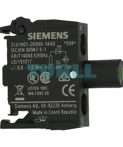
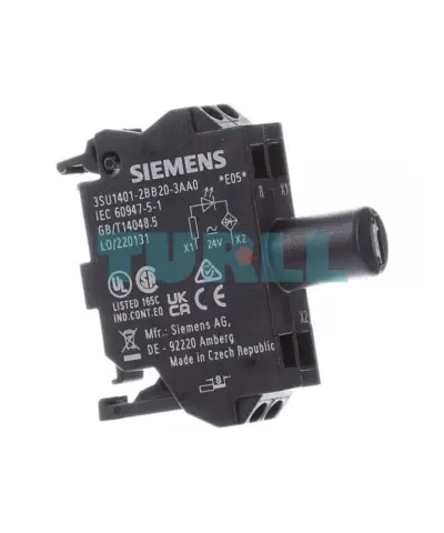
Siemens 3SU1401-1BB20-3AA0 LED Module 24V AC/DC, Red, Spring-Loaded Terminal, Front Plate Mounting Original Brand New
3SU1401-1BB20-3AA0
Original price was: $8.84.$3.54Current price is: $3.54.
In stock
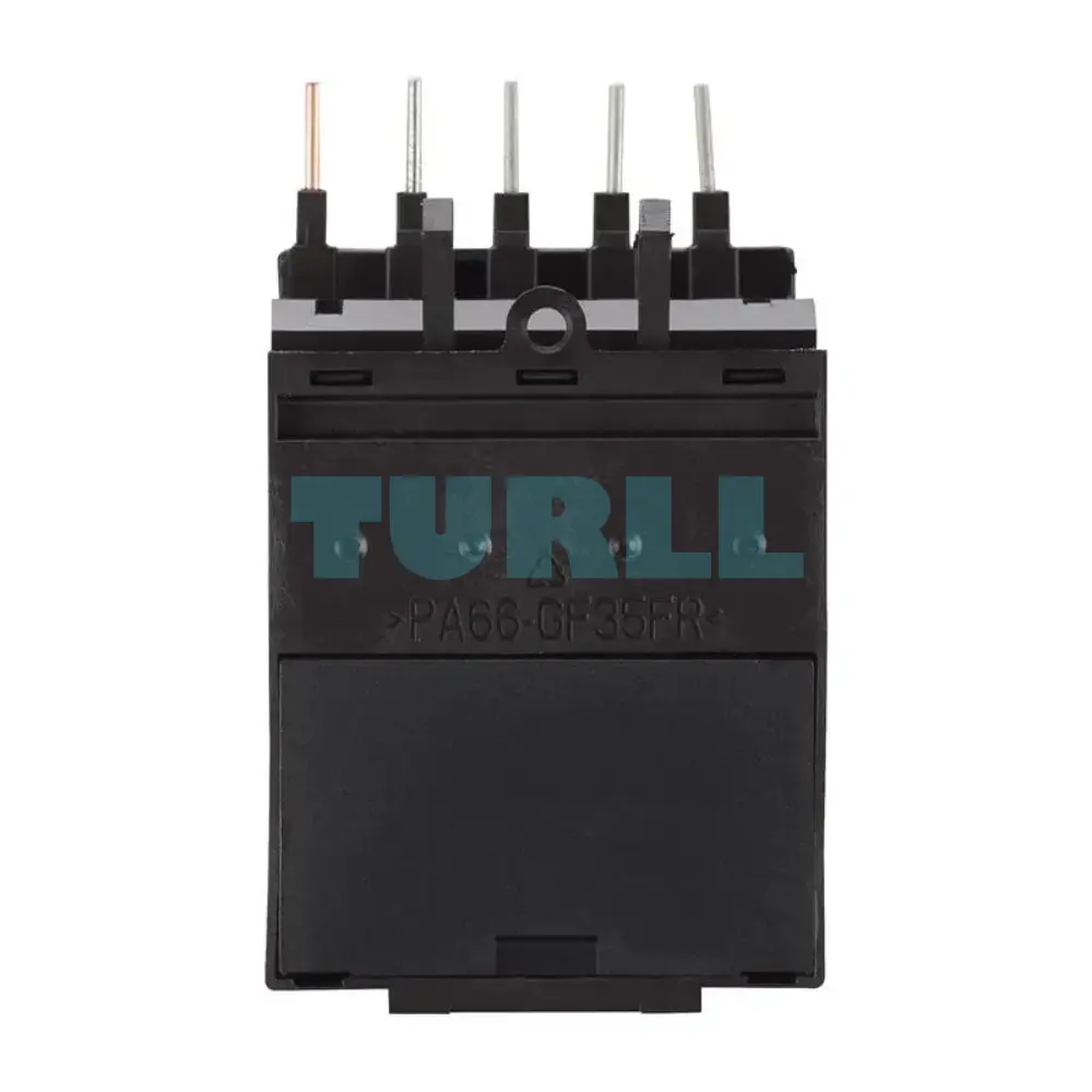
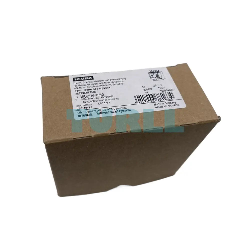
SIEMENS
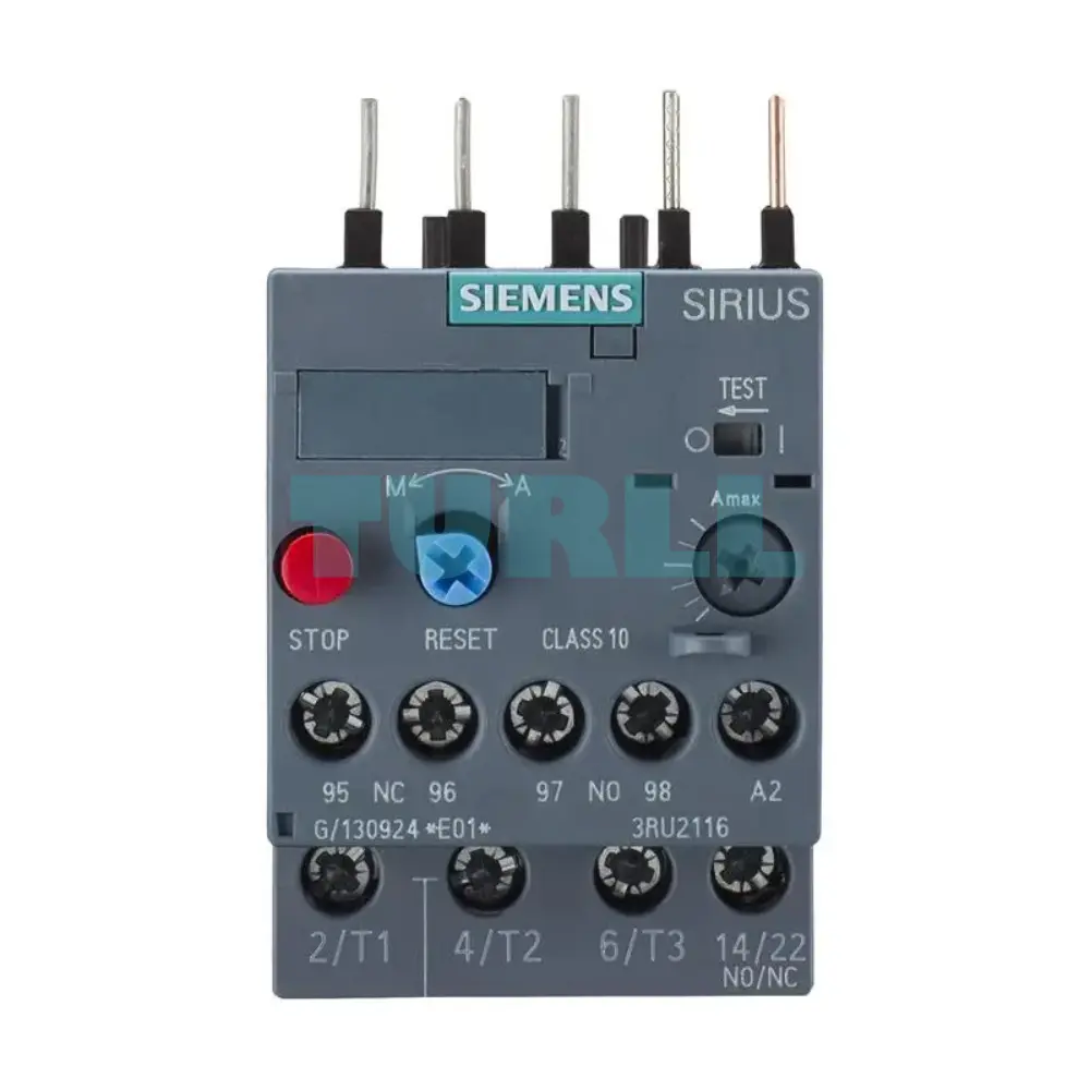
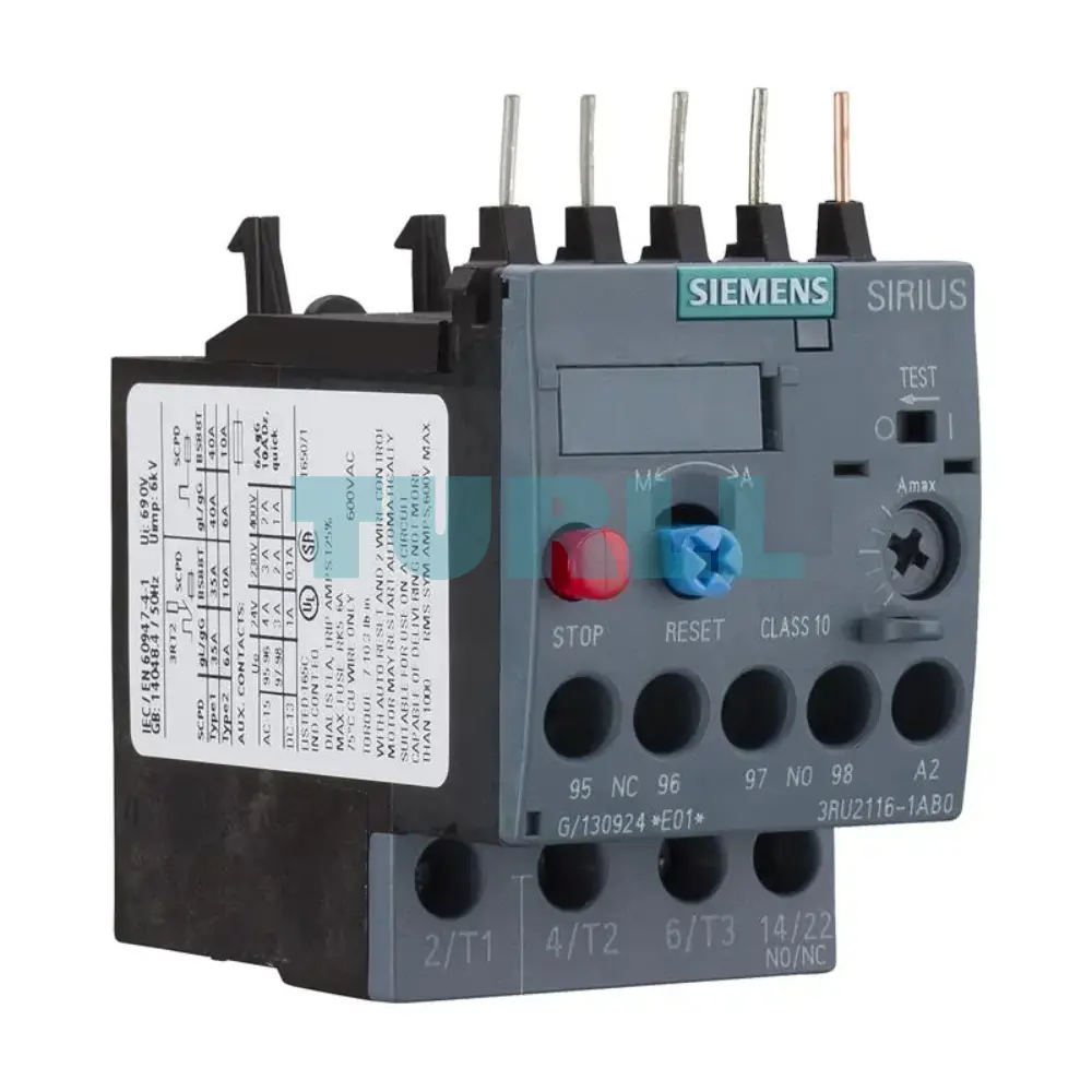
A reliable thermal overload relay from the SIRIUS line, designed for motor protection in Size S00 applications. It features an adjustable current setting of 2.8 to 4.0 A, tripping characteristic Class 10, and is suitable for direct contactor mounting. Connections are simple with screw-type terminals for both main and auxiliary circuits.
Backorder available · Factory lead time 2–3 weeks.
The Siemens 3RU2116-1EB0 is a high-performance thermal overload relay specifically engineered to protect three-phase motors against excessive heating due to overcurrent, phase failure, or heavy starting. Part of the trusted Siemens SIRIUS industrial control system, this device is crucial for maintaining the operational reliability and longevity of electrical machinery. It is optimally designed for direct mounting onto Size S00 contactors, offering a compact and streamlined installation.
Reliable Motor Protection: Prevents damage from overloads and excessive temperatures.
High Accuracy: Thermal tripping mechanism ensures stable and precise response times.
Flexible Reset Options: Includes Manual / Automatic Reset for convenience and safety.
Compact & Versatile: Designed for Size S00 applications with easy contactor mounting.
Durable Build: Siemens engineering guarantees long-term operational safety and performance.
Type: Thermal Overload Relay
Current Range: 2.8–4.0 A
Class: Class 10
Mounting: Contactor mounting (Size S00)
Main Circuit Connection: Screw terminals
Auxiliary Circuit Connection: Screw terminals
Reset Mode: Manual or Automatic
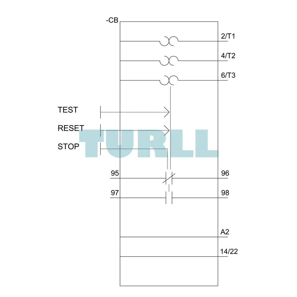
The 3RU2116-1EB0 operates on a bimetallic strip principle. When the current flowing through the main circuit terminals exceeds the set value (2.8 A to 4.0 A), the bimetal strips heat up and deform proportionally. If the overcurrent persists for a duration determined by the Class 10 trip curve, the deformation triggers a mechanism that opens the NC auxiliary contact (and closes the NO contact), immediately isolating the motor circuit by de-energizing the main contactor coil. The Manual-Automatic-Reset function determines how the relay is returned to the operational state after a trip.
Visit 3RU2116-1EB0 for more detail info
For more our products visit turll
| SKU / Model | 3RU2116-1EB0 |
|---|---|
| Brand | SIEMENS |
| product brand name | SIRIUS |
| product designation | thermal overload relay |
| product type designation | 3RU2 |
| size of overload relay | S00 |
| size of contactor can be combined company-specific | S00 |
| power loss [W] for rated value of the current at AC in hot operating state | 5.7 W |
| ● per pole | 1.9 W |
| insulation voltage with degree of pollution 3 at AC rated value | 690 V |
| surge voltage resistance rated value | 6 kV |
| maximum permissible voltage for safe isolation in networks with grounded star point | - |
| ● between auxiliary and auxiliary circuit | 440 V |
| ● between main and auxiliary circuit | 440 V |
| shock resistance acc. to IEC 60068-2-27 | 8g / 11 ms |
| type of protection according to ATEX directive 2014/34/EU | Ex II (2) GD |
| certificate of suitability according to ATEX directive 2014/34/EU | DMT 98 ATEX G 001 |
| reference code acc. to IEC 81346-2 | F |
| installation altitude at height above sea level maximum | 2 000 m |
| ambient temperature | - |
| ● during operation | -40 ... +70 °C |
| ● during storage | -55 ... +80 °C |
| ● during transport | -55 ... +80 °C |
| temperature compensation | -40 ... +60 °C |
| relative humidity during operation | 10 ... 95 % |
| number of poles for main current circuit | 3 |
| adjustable current response value current of the current-dependent overload release | 2.8 ... 4 A |
| operating voltage | - |
| ● rated value | 690 V |
| ● at AC-3 rated value maximum | 690 V |
| operating frequency rated value | 50 ... 60 Hz |
| operational current rated value | 4 A |
| operating power at AC-3 | - |
| ● at 400 V rated value | 1.5 kW |
| ● at 500 V rated value | 2.2 kW |
| ● at 690 V rated value | 3 kW |
| design of the auxiliary switch | integrated |
| number of NC contacts for auxiliary contacts | 1 |
| number of NO contacts for auxiliary contacts | 1 |
| ● note | for message "Tripped" |
| number of CO contacts for auxiliary contacts | 0 |
| operational current of auxiliary contacts at AC-15 | - |
| ● at 120 V | 3 A |
| ● at 230 V | 2 A |
| ● at 400 V | 1 A |
| operational current of auxiliary contacts at DC-13 | - |
| ● at 24 V | 2 A |
| ● at 60 V | 0.3 A |
| ● at 110 V | 0.22 A |
| ● at 125 V | 0.22 A |
| ● at 220 V | 0.11 A |
| contact rating of auxiliary contacts according to UL | B600 / R300 |
| trip class | CLASS 10 |
| design of the overload release | thermal |
| full-load current (FLA) for 3-phase AC motor | - |
| ● at 480 V rated value | 4 A |
| ● at 600 V rated value | 4 A |
| design of the fuse link | - |
| ● for short-circuit protection of the auxiliary switch required | fuse gG: 6 A, quick: 10 A |
| mounting position | any |
| fastening method | Contactor mounting |
| product component removable terminal for auxiliary and control circuit | No |
| type of electrical connection | - |
| ● for main current circuit | screw-type terminals |
| ● for auxiliary and control circuit | screw-type terminals |
| arrangement of electrical connectors for main current circuit | Top and bottom |
| ● at AWG cables for main contacts | 2x (20 ... 16), 2x (18 ... 14), 2x 12 |
| type of connectable conductor cross-sections | - |
| ● for auxiliary contacts | - |
| — solid or stranded | 2x (0.5 ... 1.5 mm²), 2x (0.75 ... 2.5 mm²) |
| — finely stranded with core end processing | 2x (0.5 ... 1.5 mm²), 2x (0.75 ... 2.5 mm²) |
| ● at AWG cables for auxiliary contacts | 2x (20 ... 16), 2x (18 ... 14) |
| tightening torque | - |
| ● for main contacts with screw-type terminals | 0.8 ... 1.2 N·m |
| ● for auxiliary contacts with screw-type terminals | 0.8 ... 1.2 N·m |
| design of screwdriver shaft | Diameter 5 ... 6 mm |
| size of the screwdriver tip | Pozidriv PZ 2 |
| design of the thread of the connection screw | - |
| ● for main contacts | M3 |
| ● of the auxiliary and control contacts | M3 |
| failure rate [FIT] with low demand rate acc. to SN 31920 | 50 FIT |
| MTTF with high demand rate | 2 280 y |
| T1 value for proof test interval or service life acc. to IEC 61508 | 20 y |
| protection class IP on the front acc. to IEC 60529 | IP20 |
| touch protection on the front acc. to IEC 60529 | finger-safe, for vertical contact from the front |
| display version for switching status | Slide switch |
| Vibration and Shock | - |
| last modified: | 12/1/2021 |
| Weight | 0.160 kg |
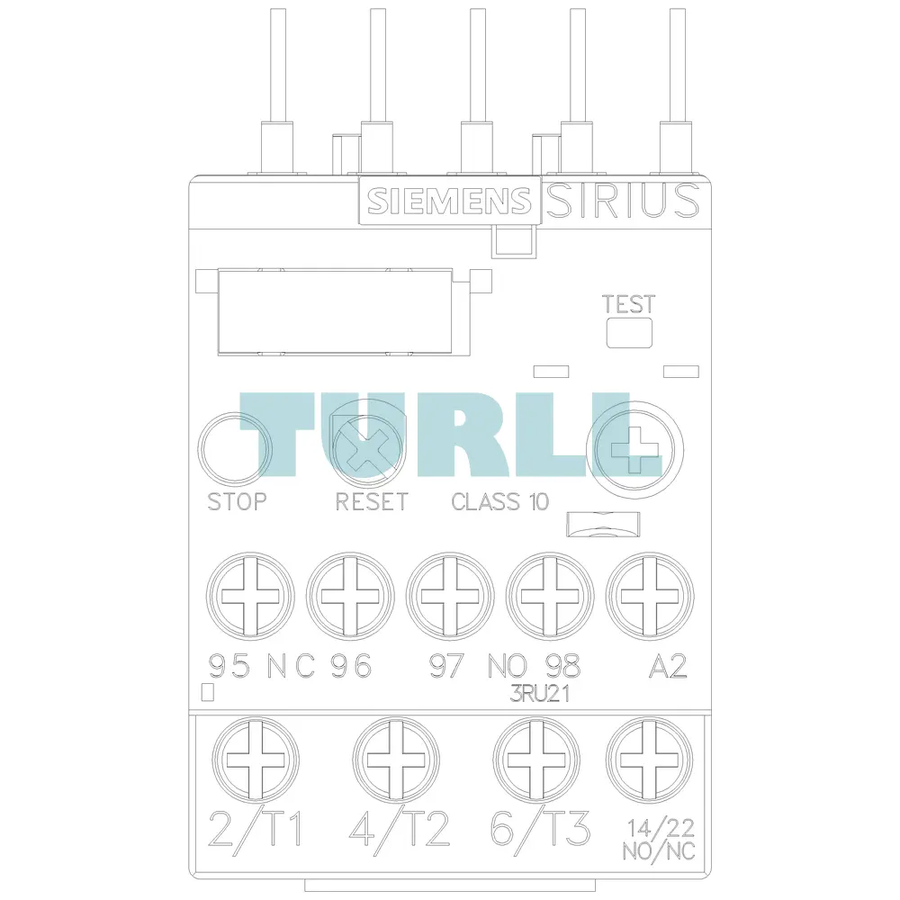
| Dimensions | 49.00 × 102.00 × 84.00 mm |
Request a quote for project quantities, discontinued or obsolete models, and pro-forma invoice / bank transfer orders. Our sourcing team responds fast.