SIEMENS
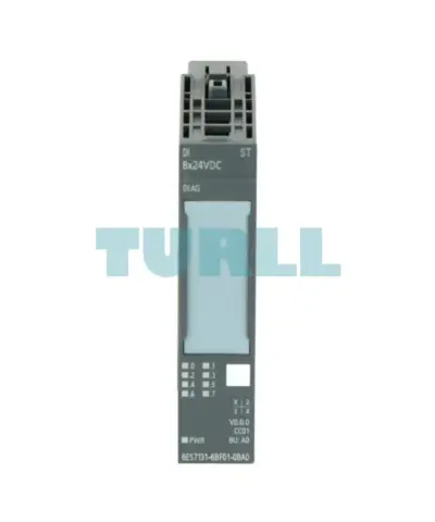
Siemens 6ES7131-6BF01-0BA0 SIMATIC ET 200SP Digital Input Module DI 8x24V DC Original Brand New
6ES7131-6BF01-0BA0
Original price was: $91.24.$42.45Current price is: $42.45.
In stock

SIEMENS
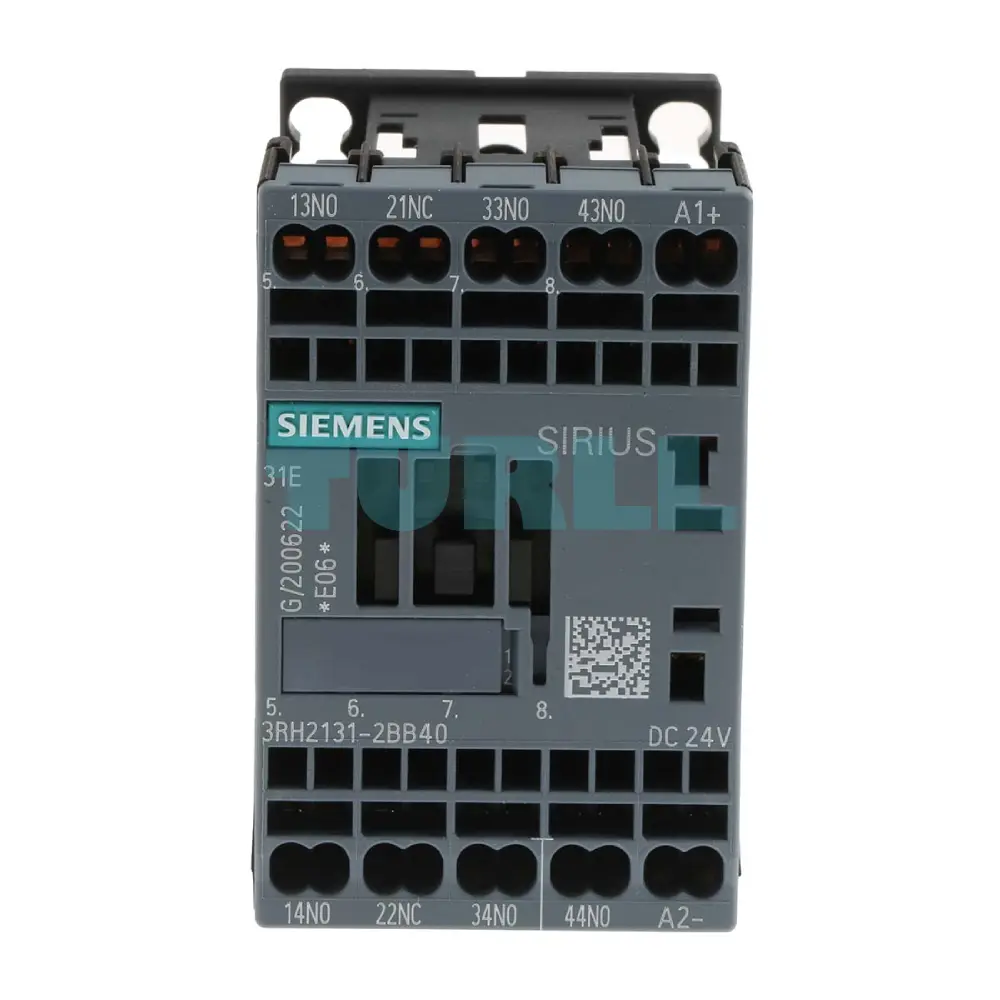
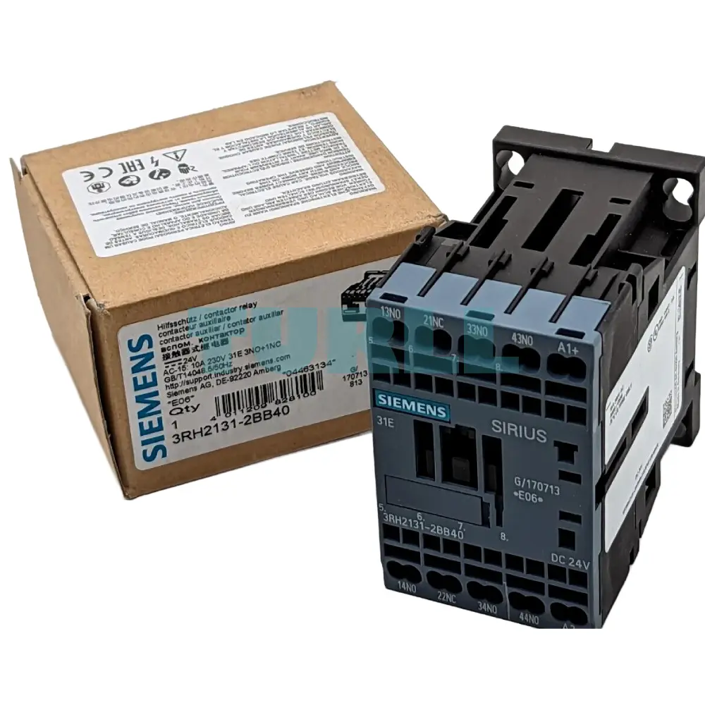
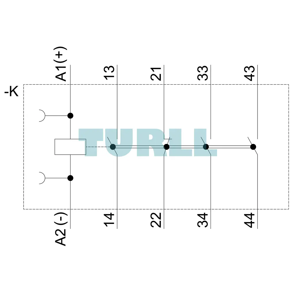
High-performance Sirius 3RH2 contactor relay designed for switching control signals in industrial environments. Featuring a 3 NO + 1 NC contact configuration and a 24V DC operating voltage, this S00 frame size unit utilizes modern spring-loaded terminals for vibration-resistant, maintenance-free wiring.
The Siemens 3RH2131-2BB40 represents the pinnacle of switching technology within the Siemens Sirius Innovation portfolio. As a dedicated contactor relay, it is engineered to provide reliable, high-speed switching of auxiliary circuits and control signals. In the world of industrial automation, the 3RH2 series, including the 3RH2131-2BB40, is synonymous with durability and modularity. The 3RH2131-2BB40 is designed to meet the demands of modern automation requirements.
This specific model operates on a 24V DC control supply, making it perfectly compatible with standard PLC (Programmable Logic Controller) outputs and low-voltage control systems. With its compact S00 frame size, it allows for high-density installation within control cabinets, saving valuable rail space without compromising on performance.
One of the standout features of the 3RH2131-2BB40 is its spring-loaded terminal system. Unlike traditional screw terminals, spring-loaded connections offer:
Vibration Resistance: Ideal for environments with heavy machinery where screws might loosen over time.
Reduced Installation Time: Facilitates faster wiring during the assembly of control panels.
Maintenance-Free Operation: Constant tension ensures a secure electrical connection for the life of the product.
Space Efficiency: The S00 frame size is one of the smallest in its class, allowing for more components per DIN rail.
Global Compliance: Fully compliant with international standards including IEC, UL, and CSA, ensuring it can be used in global export projects.
Modular Versatility: This relay can be expanded with front-mounted auxiliary switch blocks to increase the number of available contacts.
Reliability: Rated for millions of switching cycles, reducing downtime and lowering the total cost of ownership (TCO).
Energy Efficient: Optimized coil design minimizes power consumption during 24V DC operation.
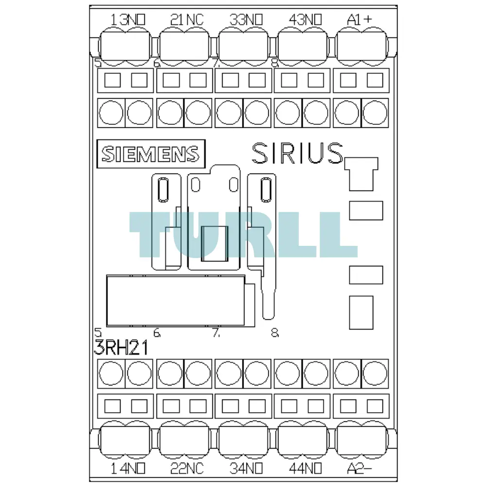
The primary function of the Siemens 3RH2131-2BB40 is the multiplication of signals. It takes a single control input (the 24V DC coil) and provides four distinct output signals (3 Normally Open and 1 Normally Closed).
Switching Frequency: Capable of high-frequency operation, suitable for rapid cycling applications.
Climate Resistance: Designed to operate in a wide range of temperatures and humidity levels, typical of harsh industrial manufacturing floors.
Integration: Features integrated surge suppression (available via accessories) to protect sensitive upstream electronic components from voltage spikes.
The 3RH2131-2BB40 is versatile enough for use across various sectors, including:
Manufacturing & Assembly: Used in motor control centers to signal the status of motors to a central control room.
HVAC Systems: Controlling auxiliary pumps, fans, and status indicators in large-scale building management systems.
Safety Logic: Implementing hardware-based interlocking logic to prevent conflicting machine operations.
Conveyor Systems: Synchronizing multiple conveyor belts by relaying start/stop signals across the system.
Renewable Energy: Used in the control panels of wind turbines and solar inverters to manage peripheral equipment.
Visit 3RH2131-2BB40 for more detail info
For more our products visit turll
| SKU / Model | 3RH2131-2BB40 |
|---|---|
| Brand | SIEMENS |
| product brand name | SIRIUS |
| product designation | Auxiliary contactor |
| product type designation | 3RH2 |
| size of contactor | S00 |
| product extension auxiliary switch | Yes |
| insulation voltage with degree of pollution 3 at AC rated value | 690 V |
| degree of pollution | 3 |
| surge voltage resistance rated value | 6 kV |
| shock resistance at rectangular impulse | - |
| shock resistance with sine pulse | - |
| mechanical service life (switching cycles) | - |
| ● of contactor typical | 30 000 000 |
| ● of the contactor with added electronically optimized auxiliary switch block typical | 5 000 000 |
| ● of the contactor with added auxiliary switch block typical | 10 000 000 |
| reference code acc. to IEC 81346-2 | K |
| installation altitude at height above sea level maximum | 2 000 m |
| ambient temperature | - |
| ● during operation | -25 ... +60 °C |
| ● during storage | -55 ... +80 °C |
| relative humidity minimum | 10 % |
| relative humidity at 55 °C acc. to IEC 60068-2-30 maximum | 95 % |
| no-load switching frequency | - |
| ● at AC | 10 000 1/h |
| type of voltage of the control supply voltage | DC |
| control supply voltage at DC | - |
| ● rated value | 24 V |
| operating range factor control supply voltage rated value of magnet coil at DC | - |
| ● initial value | 0.8 |
| ● full-scale value | 1.1 |
| closing power of magnet coil at DC | 4 W |
| holding power of magnet coil at DC | 4 W |
| closing delay | - |
| opening delay | - |
| ● at DC | 7 ... 13 ms |
| arcing time | 10 ... 15 ms |
| number of NC contacts for auxiliary contacts | 1 |
| number of NO contacts for auxiliary contacts | 3 |
| ● instantaneous contact | 3 |
| identification number and letter for switching elements | 31 E |
| operational current at AC-12 maximum | 10 A |
| operational current at AC-15 | - |
| ● at 230 V rated value | 10 A |
| ● at 400 V rated value | 3 A |
| ● at 500 V rated value | 2 A |
| ● at 690 V rated value | 1 A |
| operational current at 1 current path at DC-12 | - |
| operational current with 2 current paths in series at DC-12 | - |
| operational current with 3 current paths in series at DC-12 | - |
| operating frequency at DC-12 maximum | 1 000 1/h |
| operational current at 1 current path at DC-13 | - |
| operational current with 2 current paths in series at DC-13 | - |
| operational current with 3 current paths in series at DC-13 | - |
| ● at 24 V rated value | 10 A |
| ● at 60 V rated value | 4.7 A |
| ● at 110 V rated value | 3 A |
| ● at 220 V rated value | 1.2 A |
| ● at 440 V rated value | 0.5 A |
| ● at 600 V rated value | 0.26 A |
| operating frequency at DC-13 maximum | 1 000 1/h |
| design of the miniature circuit breaker for short-circuit protection of the auxiliary circuit up to 230 V | C characteristic: 6 A; 0.4 kA |
| contact reliability of auxiliary contacts | 1 faulty switching per 100 million (17 V, 1 mA) |
| contact rating of auxiliary contacts according to UL | A600 / Q600 |
| design of the fuse link for short-circuit protection of the auxiliary switch required | fuse gL/gG: 10 A |
| mounting position | +/-180° rotation possible on vertical mounting surface; can be tilted forward and backward by +/- 22.5° on vertical mounting surface |
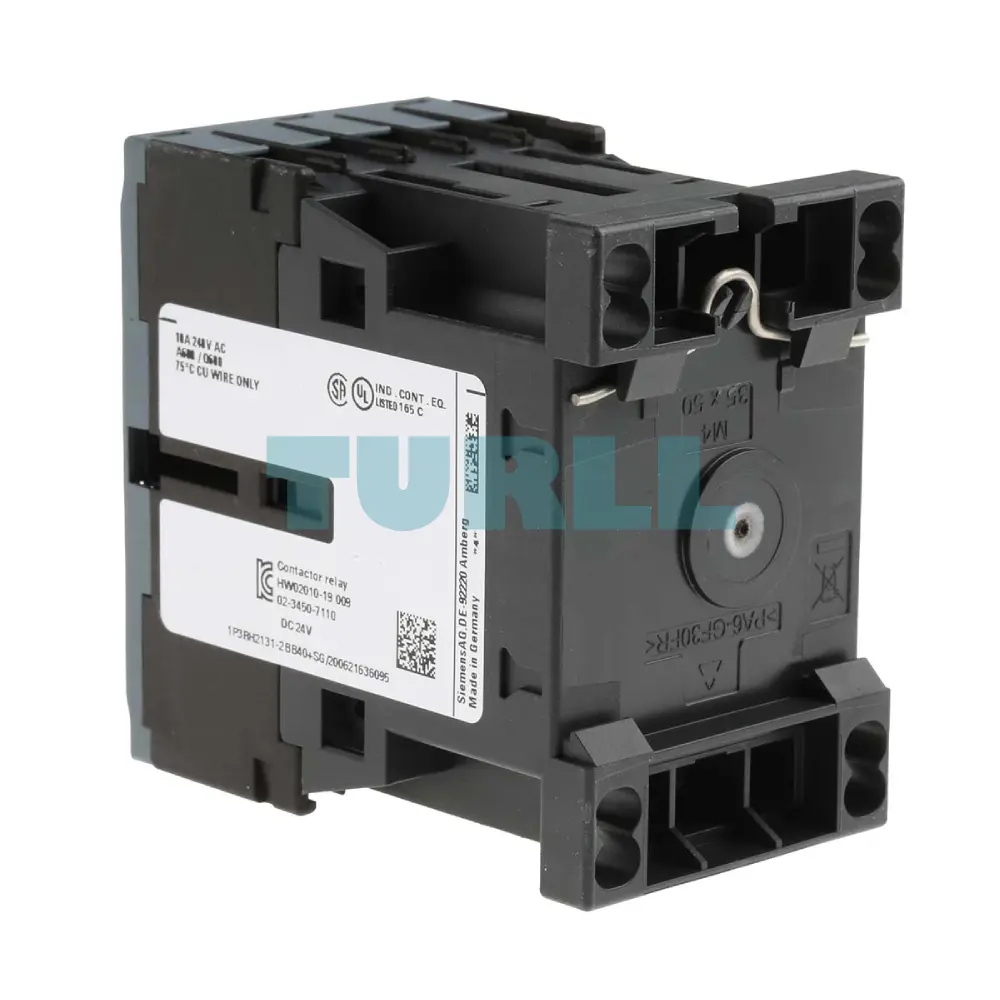
| fastening method | screw and snap-on mounting onto 35 mm standard mounting rail |
| required spacing | - |
| ● with side-by-side mounting | - |
| ● for grounded parts | - |
| ● for live parts | - |
| — forwards | 10 mm |
| — upwards | 10 mm |
| — downwards | 10 mm |
| — at the side | 6 mm |
| type of electrical connection for auxiliary and control circuit | spring-loaded terminals |
| type of connectable conductor cross-sections | - |
| ● for auxiliary contacts | - |
| — solid or stranded | 2x (0,5 ... 4 mm²) |
| — finely stranded with core end processing | 2x (0.5 ... 2.5 mm²) |
| — finely stranded without core end processing | 2x (0.5 ... 2.5 mm²) |
| ● at AWG cables for auxiliary contacts | 2x (20 ... 12) |
| B10 value with high demand rate acc. to SN 31920 | 1 000 000; With 0.3 x Ie |
| proportion of dangerous failures | - |
| ● with low demand rate acc. to SN 31920 | 40 % |
| ● with high demand rate acc. to SN 31920 | 73 % |
| failure rate [FIT] with low demand rate acc. to SN 31920 | 100 FIT |
| T1 value for proof test interval or service life acc. to IEC 61508 | 20 y |
| protection class IP on the front acc. to IEC 60529 | IP20 |
| touch protection on the front acc. to IEC 60529 | finger-safe, for vertical contact from the front |
| other | Dangerous Good |
| last modified: | 11/10/2021 |
| Weight | 0.289 kg |
| Dimensions | 50.00 × 73.50 × 77.50 mm |
Request a quote for project quantities, discontinued or obsolete models, and pro-forma invoice / bank transfer orders. Our sourcing team responds fast.