


6AG2136-6DB00-1CA0 Siemens SIPLUS ET 200SP F-DQ Original Brand New
$1,484.91
6AG2136-6DB00-1CA0
Siemens SIPLUS ET 200SP F-DQ 4x24VDC/2A PM rail based on 6ES7136-6DB00-0CA0 with conformal coating, -30…+60 °C, OT1 with ST1/2 (+70 °C für 10 minutes), fail-safe digital outputs up to PL e (ISO 13849), up to SIL 3 (IEC 61508)

[ez-toc]
Overview
Important properties:
- 4-channel digital fail-safe output module for SIPLUS extreme ET 200SP RAIL
- Approved in accordance with EN 50155, EN 15121, EN 50124, EN 50125 and EN 45545 railway standards for use in rail traffic
- Fail-safe 2-channel activation (sinking/sourcing output) by actuators
- Actuators can be controlled up to 2 A or 0.5 A
- Certified up to SIL 3 (IEC 61508), PL e (ISO 13849)
- Can be plugged into type A0 BaseUnits (BU) with automatic coding
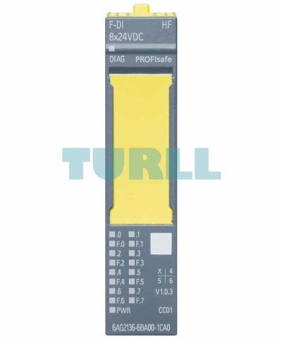
- LED display for error, operation, supply voltage and status
- Clear labeling on front of module
- Plain text identification of the module type and function class
- 2D matrix code (order and serial number)
- Connection diagram
- Color coding of the DI module type: White
- Hardware and firmware version
- CC color code for module-specific color coding of the potentials at the terminals of the BU
- Complete Article No.
- Optional labeling accessories
- Labeling strips
- Equipment labeling plate
- Optional module-specific color identification of the terminals according to the color code CC
- Optional system-integrated shield connection
- The modules support PROFIsafe in both PROFIBUS and PROFINET configurations
- They can be used with all fail-safe SIMATIC S7 CPUs
Application
The fail-safe modules of SIPLUS extreme ET 200SP RAIL can be used to implement the safety-related application requirements as an integral part of the overall automation. The safety functions required for fail-safe operation are integrated in these modules. Communication with the fail-safe SIMATIC S7 CPUs is performed by means of PROFIsafe.
The modules can be operated both in centralized and distributed configurations.
Design
Suitable BaseUnits
BaseUnits with an appropriate number of terminals are available for single and multi-conductor connections.
A light BaseUnit opens a new load group. The supply voltage to the sensors must be fed via this BU. The first BU next to the interface module must always be a light BU.
A dark BaseUnit forwards the supply voltage of the adjacent light BaseUnit on the left via self-assembling voltage buses. A new infeed is therefore only required on the next light BaseUnit to the right.
All variants that correspond to the BU type of the I/O module can be used as BaseUnits.
Color coding of the terminals
The potentials at the terminals of the BaseUnit are defined by the I/O module. Optionally, the potentials of the terminals can be identified by module-specific color-coding labels to prevent wiring errors. The color-coded label that matches the respective I/O module is defined by the color code CCxx of the I/O module. This color code is also printed on the front of the module.
In BaseUnits with the 10 internally jumpered AUX terminals, these can also be identified with color-coding labels. For the 10 AUX terminals, color-coding labels are available in red, blue, and yellow/green.
System-integrated shield connection
For the space-saving and EMC-optimized connection of cable shields, a shield connection is available that is quick and easy to mount. This consists of one shield connection element that can be plugged onto the BaseUnit and one shield terminal for each module. The low-impedance connection to the functional ground (DIN rail) is achieved without any additional wiring by the user.
6AG2136-6DB00-1CA0
Siemens SIPLUS ET 200SP F-DQ 4x24VDC/2A PM rail based on 6ES7136-6DB00-0CA0 with conformal coating, -30…+60 °C, OT1 with ST1/2 (+70 °C für 10 minutes), fail-safe digital outputs up to PL e (ISO 13849), up to SIL 3 (IEC 61508)
Visit 6AG2136-6DB00-1CA0
For more our products visit turll.com
| Weight | 0.076 kg |
|---|---|
| Dimensions | 65 × 88 × 38 mm |
You must be logged in to post a review.
Reviews
There are no reviews yet.