


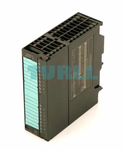
6ES7374-2XH01-0AA0 Siemens SIMATIC S7-300 SM 374 Original Brand New
$496.51
6ES7374-2XH01-0AA0 Siemens
SIMATIC S7-300, simulator module SM 374, for simulation of 16 inputs or 16 outputs or 8 inputs and 8 outputs 16 switches, 16 LEDs

Overview
- Simulator module for program testing during commissioning and ongoing operation
- For the simulation of sensor signals using switches
- For display of signal conditions on the outputs using LED
- Simulation of
- 16 inputs or
- 16 outputs or
- 8 inputs and 8 outputs
- Function can be directly adjusted on the module using a screwdriver
Application
The SM 374 simulator module provides the user with a convenient means of testing his/her programs during startup and operation.
Design
Located on the front panel of the module are:
- Switches for input status:
16 switches are used to simulate input signals. - LEDs for output status:
16 LEDs indicate the signal status at the outputs. - Mode selector:
The user can set one of the following three modes using a screwdriver:- 16 inputs (input simulation only),
- 16 outputs (output simulation only),
- 8 inputs (input and output simulation) and
- 8 outputs (input and output simulation).
These operating elements are protected by the front cover. The module is snapped onto the rail and connected to the S7-300 backplane bus. The power is supplied via the backplane bus.
Function
- Simulation of sensor signals over switches
- Display of signal states on outputs with LEDs
Mode of operation
The module is installed in place of a digital input or digital output module in the S7-300. This enables the user to influence the program execution by setting the inputs.
The CPU reads the set input signal states of the simulator module and processes them in the user program. The output signal states are then sent to the module where LEDs indicate the signal status. This allows conclusions to be drawn about the program sequence.
6ES7374-2XH01-0AA0 Siemens
| Weight | 0.255 kg |
|---|---|
| Dimensions | 128 × 152 × 50 mm |
You must be logged in to post a review.

Reviews
There are no reviews yet.