


6AG1137-6BD00-2BA0 Siemens SIPLUS ET 200SP CM 4xIO-LINK Original Brand New
$1,030.60
6AG1137-6BD00-2BA0
Siemens SIPLUS ET 200SP CM 4xIO-LINK based on 6ES7137-6BD00-0BA0 with conformal coating, -40…+60 °C, communication module IO-Link master V1.1

[ez-toc]
Overview
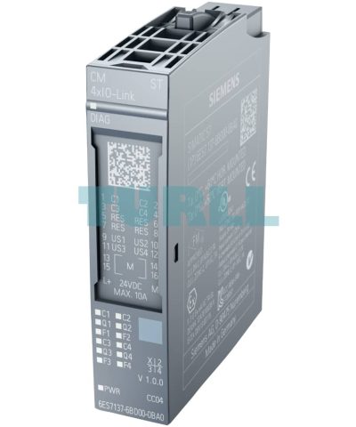
- SIPLUS CM 4x IO-Link communications module
Serial communications module for connecting up to 4 IO-Link devices in accordance with IO-Link specification V1.0 and V1.1. The IO-Link parameters are configured using the Port Configuration Tool (PCT), version V3.0 and higher. - Time-based IO
Time-based IO ensures that signals are output with a precisely defined response time. By combining inputs and outputs, for example, passing products can be accurately measured or liquids dosed in precise quantities. - Supported data transfer rates
- COM1 (4.8 kBd)
- COM2 (38.4 kBd)
- COM3 (230.4 kBd)
- Expansion limits
- Cable length: Max. 20 m
- Max. 32 bytes of input and output data per port
- Max. 144 bytes of input data and 128 bytes of output data per module
- Supported ET 200SP system functions
- Replacement without PG with automatic backup without the engineering tool of the IO-Link Device Parameter (V1.1 devices only) and the IO-Link master parameters by means of redundant saving of parameters on the e-coding element
- Re-parameterization during operation
- Identification data I&M
- Firmware update
- PROFIenergy
- Can be plugged into Type A0 BaseUnits (BU) with automatic e-coding
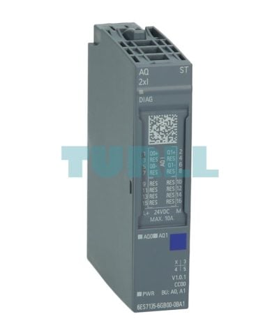
- LED displays
- DIAG: Operating state display (green/red) of the module
- C1..C4: Port status indicator (green) for Port 1, 2, 3 and 4
- Q1..Q4: Channel status indicator (green) for Port 1, 2, 3 and 4
- F1..F4: Port fault indicator (red) for Port 1, 2, 3 and 4
- PWR: Supply voltage indicator (green)
- Clear labeling on front of module
- Plain text identification of the module type and function class
- 2D matrix code (order and serial number)
- Connection diagram
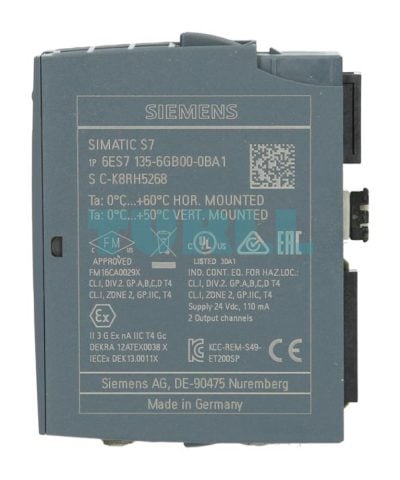
- Color-coding of the module class CM: silver
- Hardware and firmware version
- Complete Article No.
- Optional accessories
- Labeling strips
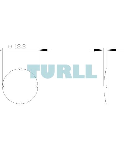
- Equipment labeling plate
- Color-coded label with color code CC04
- Optional system-integrated shield connection
Application
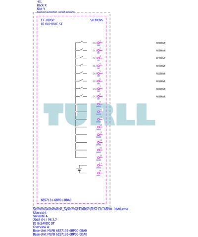
- The CM 4x IO-Link communications module enables data exchange with up to 4 external IO-Link devices via one 3-wire cable each.
- Comprehensive parameterization options make it possible to adapt the controller flexibly to the communication partner.
- Thanks to the compatibility of IO-Link with standard sensors, commercially available sensors in accordance with IEC 61131 Type 1 can also be operated on the IO-Link master.
Design
Suitable BaseUnits (BU)
All BUs of type A0 are available for the communications module CM 4x IO-Link.
Load group formation
A light-colored BU separates the self-assembling, internal voltage buses (P1, P2, AUX) and thus opens a new load group. The supply voltage of a load group must be fed in at the light BU of this load group.
A dark BU forwards the supply voltage of the adjacent light BU on the left via the self-assembling voltage buses P1, P2 and AUX. A new infeed is therefore only required on the next light BU to the right. The setting of a further light BU is required whenever
- a new load group is to be formed (for example, for isolating the supply voltage from module groups) or
- the maximum current simultaneously required by the load group exceeds the permissible limit of 10 A.
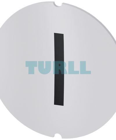
Color coding of the terminals
The potentials at the terminals of the BaseUnit are defined by the inserted I/O module in each case. To prevent wiring faults, the potentials of the terminals can optionally be identified by means of module-specific color-coded labels. The color-coded label that matches the respective I/O module is defined by the color code CCxx of the I/O module. This color code is also printed on the front of the module.
For the communications module “CM 4x IO-Link”, the color-coded label with the color code CC04 is to be used.
In BaseUnits with the additional ten internally jumpered AUX terminals, these can also be identified with color-coded labels. For the ten AUX terminals, color-coded labels are available in red, blue, and yellow/green.
Labeling
Labeling strips
Labeling strips can be inserted on the front of the interface modules or I/O modules and individually labeled via STEP 7, macros, etc. No special additional holder is required. If required, they can be easily replaced with the component.
Equipment labeling plates
Equipment labeling plates enable the equipment to be easily identified (e.g. compliant with EN 81346). They are easily plugged onto the required component (interface modules, I/O modules and BaseUnits) and when required, they can be easily replaced with the component.
The following labeling components are available:
- Foil labeling strips, light-gray, roll with 500 strips, perforated, for thermal transfer printers
- Foil labeling strips, yellow, roll with 500 strips, perforated, for thermal transfer printers
- Card labeling strips (180 g/m2), light gray, DIN A4 sheets with 100 strips each, perforated, for laser printer
- Card labeling strips (180 g/m2), yellow, DIN A4 sheets with 100 strips each, perforated, for laser printer
- Equipment labeling plates, white, ten sheets each with 16 labels, for thermal transfer card printers or labels
System-integrated shield connection
For the space-saving and EMC-optimized connection of cable shields, a shield connection is available that is quick and easy to mount. This consists of one shield connection element that can be plugged onto the BaseUnit and one shield terminal for each module. The low-impedance connection to the functional ground (DIN rail) is achieved without any additional wiring by the user.
6AG1137-6BD00-2BA0
Siemens SIPLUS ET 200SP CM 4xIO-LINK based on 6ES7137-6BD00-0BA0 with conformal coating, -40…+60 °C, communication module IO-Link master V1.1
Visit 6AG1137-6BD00-2BA0
For more our products visit turll.com
| Weight | 0.041 kg |
|---|---|
| Dimensions | 70 × 77 × 24 mm |
You must be logged in to post a review.

Reviews
There are no reviews yet.